This thread has been locked.

If you have a related question, please click the "Ask a related question" button in the top right corner. The newly created question will be automatically linked to this question.

UCC21520: Input managing with AND logic gates SN74LVC2G08

Part Number: UCC21520
Other Parts Discussed in Thread: SN74LVC2G08,

Hello!

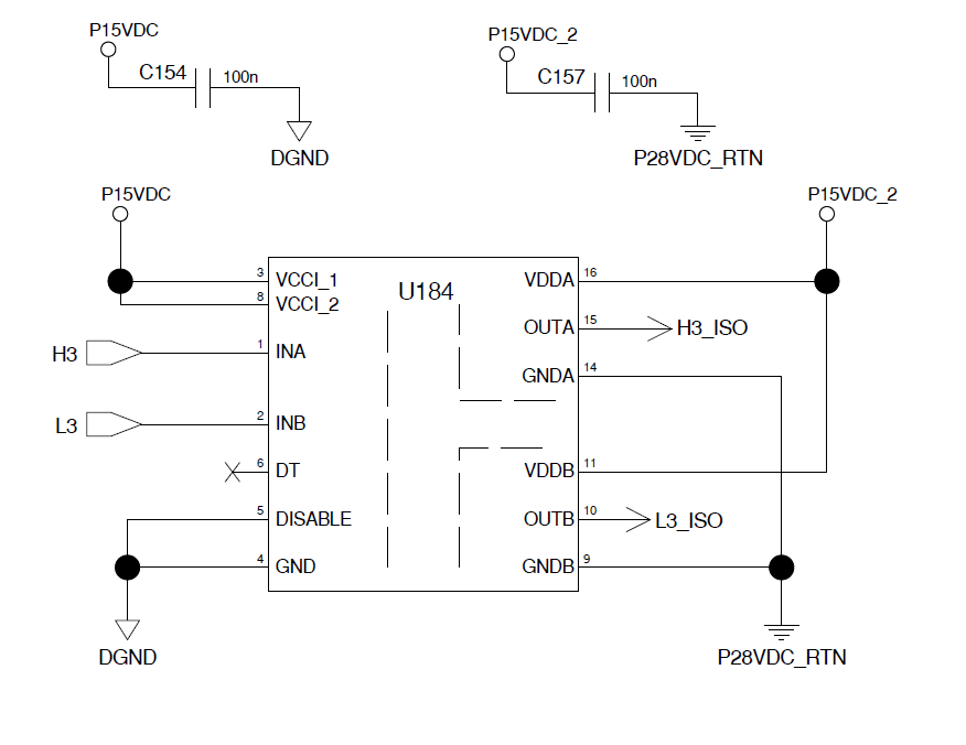
I am using the UCC2150 to manage a H-BRIDGE connected to a brushless motor (Power side).

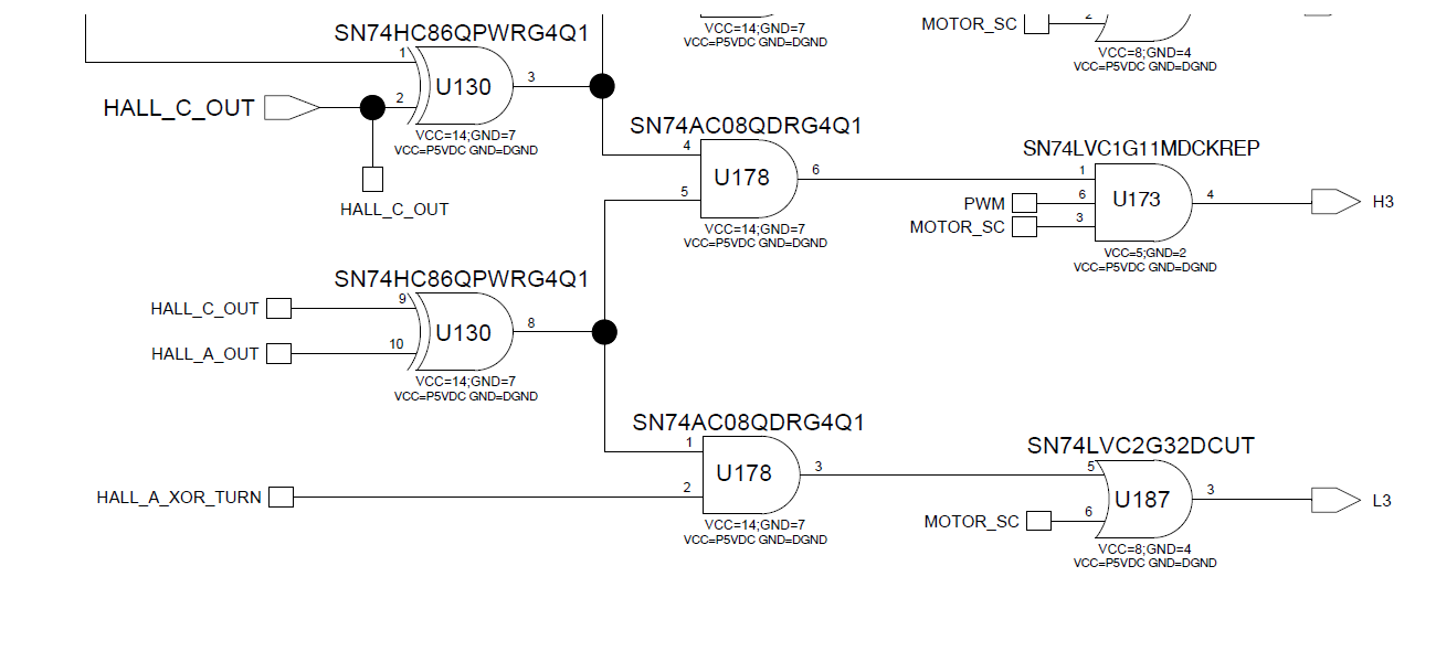
To attack H(INA) and L(INB) inputs (isolated signal side) i am using a logic to decode the hall sensor sequence (SN74LVC2G08).

The UCC2150 is powered with 5V in signal side and 15V in power side.

With a few minutes managing the motor, the AND logic gates (SN74LVC2G08) begin to warm up and finally they break. (logic output fixed to 2.5V)

I don´t know what is happening with this logic Gates. Apparently is not neccesary to include any serial resistor.

Thanks

  • Hi Luis,

    I am an applications engineer supporting isolated gate drivers. Sorry to hear you're having trouble driving the inputs with SN74LVC2G08.

    • What is your operating frequency?
    • Have you probed the inputs, outputs, and SN74LVC2G08 supply pins, with a small measurement loop, directly on the IC pins? Have you seen any voltages which exceed the absolute maximum ratings? If so, can you provide a waveform?
    • Can you please double-check the schematic and layout to confirm that the SN74LVC2G08 outputs are not shorted to VCC, GND, or each other?
    • Can you please provide a schematic of the input connection?

    Regards,

  • Hello!

    First to all, thanks for supporting me.

    The H signals switchings frequency is 9KHz (PWM SIGNAL) and the L signals is 1.5KHz (Motor speed dependent).

    I don´t have problem with H signals, only with L.

    Motor_SC signal is put to VCC in order to simplifly.

    I have removed the U187 (SN74VC2G32DCUT) and i am using U178 (SN74AC08QDRG4Q1) directly to UCC21520 and thats gate broke only one time. (Only the implicated gate, not the full component)

    I have checked the schematic and the layout some times and i have not found errors... I can only add that the track length (L3 and H3) are 40 or 50mm through a cable connector

  • Hi Luis,

    Is the DGND connection between UCC21520 and the logic gates also tied together with a cable connector? Loop inductance between UCC21520 and the logic gates may be causing voltage spikes on the outputs of the logic gates, which could be damaging them. If there are fast common mode transients between DGND and P28VDC_RTN, these common mode transients could also be coupling through the inputs of UCC21520 and damaging the logic gates. The datasheet recommends small input filters at the inputs of UCC21520, which can help to minimize detrimental inductive effects due to remote inputs. Can you try placing small input filters on the inputs? Please refer to UCC21520 datasheet section 9.2.2.1 for more information.

    Regards,
  • Hello!!!,

    I will try it and say here.

    Thanks a lot.