This thread has been locked.

If you have a related question, please click the "Ask a related question" button in the top right corner. The newly created question will be automatically linked to this question.

TCA9555: Stop generating interrupt after few input changes

Part Number: TCA9555

Hi,

i have configured TCA9555 port 0 as input and port 1 the first 4 pins configured as input and rest of the pins configured as output. TCA9555 is used along with TM4C292NCPDT for input operation. The device is generating the interrupt continuously as long as if we give input in either one of the port making all pins HIGH or LOW. but if we give inputs with combination of two ports over the minute period, its failing to generate the interrupt after either Master reads ports status  or port input status changes. the interrupt pin is always de-asserted.

Can anyone suggest what could be the reason for this behavior?

Regards

Bala

  • Hi Bala,

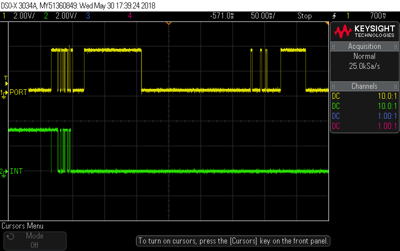
    That sounds strange, I can't think of what might cause a device to stop generating interrupts. Just to isolate the problem, do you think you could probe the INT output along with one of the inputs that you expect to be toggling so that we can clearly see that INT is not responding correctly? I want to make sure that the inputs change state and remain in the new state long enough to trigger an interrupt.

    Max
  • Hello Max,

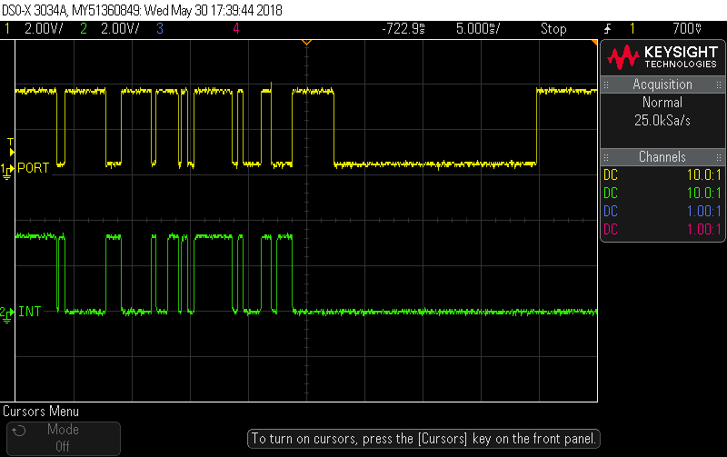
    Find the scope capture of INT pin and one of the port pin.

    Zoomed Image 

    Regards

    Bala

  • Bala,

    My initial thoughts:
    The easiest way to this kind of situation to happen is if you write to the device instead of read and set the device to an output through the configuration register. When this device's GPIOs are set to an output, then the INT pin would stop flagging though I believe the INT pin should remain high if that were the case......

    I would like to double check this just in case though, can you provide a scope shot of a read transaction of the configuration register?

    Another thought would be to look at the Vcc and Reset pins on an o-scope just before this happens to see if anything unusual is occurring.
    -----------------------------------------------------------------------------------------------------------
    Are you able to provide us with a schematic here? If not we can try to do this over email.

    Also, how are you flipping the logic on the ports? Example: Are you just tying a wire from the port pin x to GND and Vcc, are you hooking it up to an mcu and having it toggle it it's output to high or low, or is this hooked up to some sensor?

    Thanks,
    -Bobby
  • Hello Bobby,

    Bobby Nguyen said:
    My initial thoughts:
    The easiest way to this kind of situation to happen is if you write to the device instead of read and set the device to an output through the configuration register. When this device's GPIOs are set to an output, then the INT pin would stop flagging though I believe the INT pin should remain high if that were the case......

    We define the port I/O configuration upon the system initialization – this does not change in run time.

    Bobby Nguyen said:
    Another thought would be to look at the Vcc and Reset pins on an o-scope just before this happens to see if anything unusual is occurring.

    This device does not have a reset pin.

    Bobby Nguyen said:
    Are you able to provide us with a schematic here? If not we can try to do this over email.

    please share your email so that i can share the schematic.

    Bobby Nguyen said:
    Also, how are you flipping the logic on the ports? Example: Are you just tying a wire from the port pin x to GND and Vcc, are you hooking it up to an mcu and having it toggle it it's output to high or low, or is this hooked up to some sensor?

    All of port A is configured as input. Part of port B is input. This is a static configuration , does not change. The outputs drive the gate of the mosfet. Inputs are at logic levels, confirmed by scope measurements. 

    Regards

    Bala

  • Hey Bala,

    "We define the port I/O configuration upon the system initialization – this does not change in run time."
    -I wanted to be sure that you are not accidentally writing when you go to read as I have seen customers sometimes make coding errors resulting in writes. I don't think this is the issue either but I wanted to double check.

    "This device does not have a reset pin."
    -Woops. You are right....

    "please share your email so that i can share the schematic."
    duynguyen@ti.com

    "All of port A is configured as input. Part of port B is input. This is a static configuration , does not change. The outputs drive the gate of the mosfet. Inputs are at logic levels, confirmed by scope measurements. "
    Your scope shot shows the port is changing from high to low over time so I am wondering what you are doing on the port. (pressing a button connected to GND while other side has a pull up?) I assume I will be able to see what they are connected to with your schematic though.

    Thanks,
    -Bobby
  • Hello Bobby,

    Bobby Nguyen said:
    -I wanted to be sure that you are not accidentally writing when you go to read as I have seen customers sometimes make coding errors resulting in writes. I don't think this is the issue either but I wanted to double check.

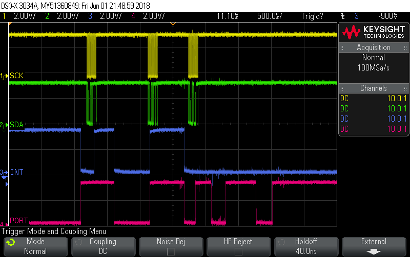
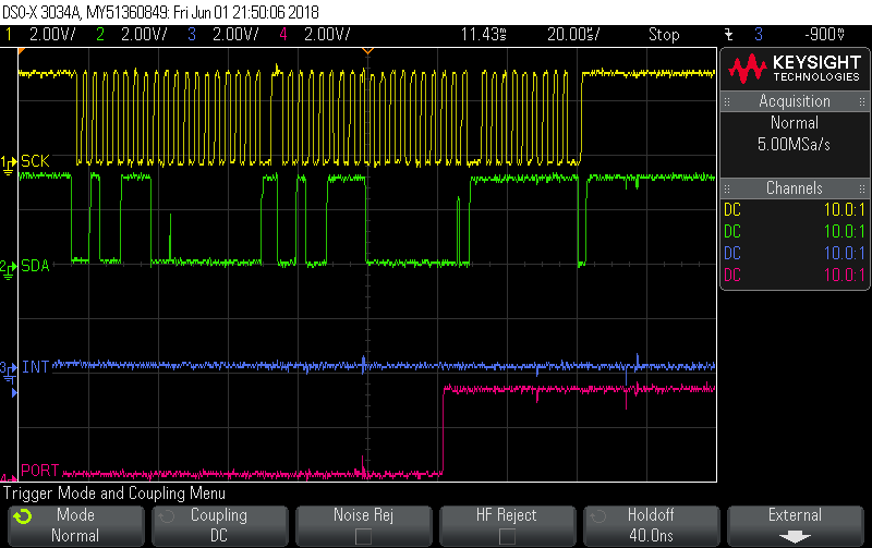
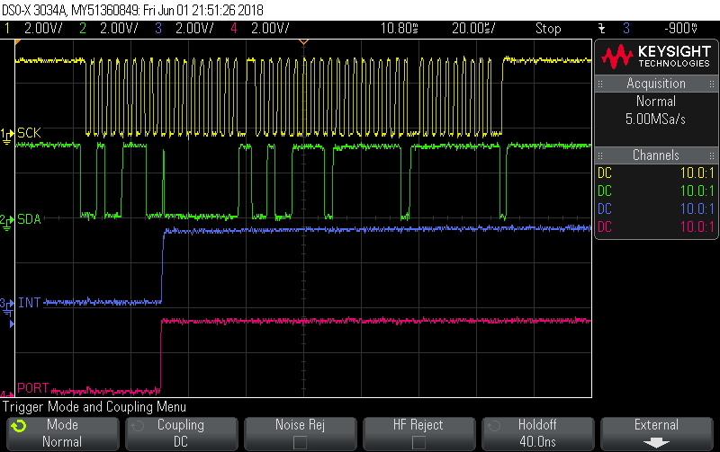
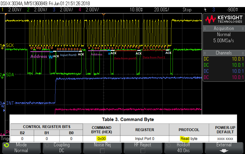
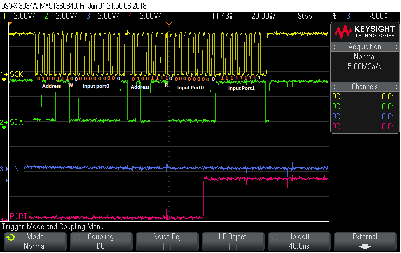
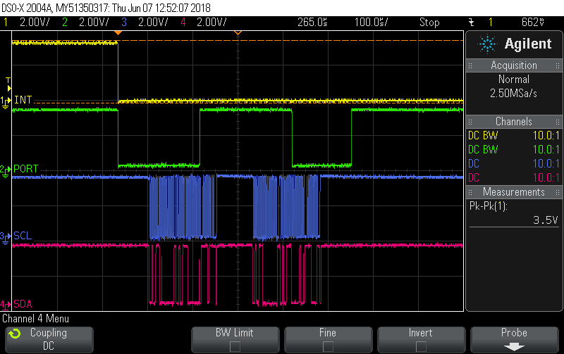
    here is the scope capture for better understanding. this time with SCL and SDA.

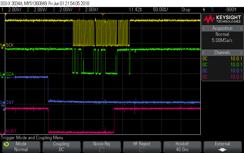
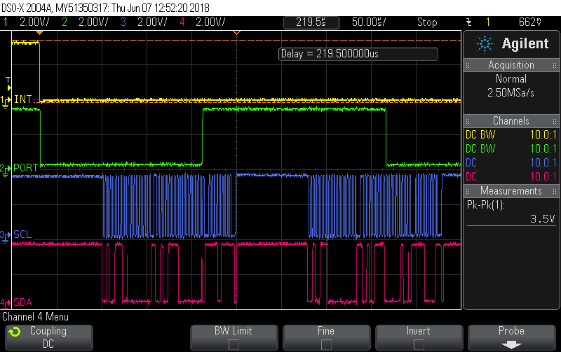
    This is zoomed version of last interrupt.

    Zoomed image of last I2C transaction after last interrupt.

    Last before I2C tranaction


    Bobby Nguyen said:
    Your scope shot shows the port is changing from high to low over time so I am wondering what you are doing on the port. (pressing a button connected to GND while other side has a pull up?) I assume I will be able to see what they are connected to with your schematic though.

    This is the external input, we dont know what is the exact input. to simulate we generated the generic pulses.

    i will share the schematic over the mail.

    My observation from the scope, when the last I2C read data should be all LOW. but only port 0 is getting LOW and port 1st retaining the last state i.e. HIGH. This is the common scenario when interrupt is not generating. i.e. any one of port is not changed to new state or withing port itself some of the pins are getting changed to the new state and some of the pins are retaining the old state.

    Regards

    Bala

  • The situation seems to be a bit different than the preceding interpretations.

    First, INT(bar) is active low, not active high.  So the problem is not that the interrupt is not being asserted, instead it remaining asserted.

    Second, without doing a detailed bit bit analysis of the data transfer, the data transfer seems almost normal ( but see fifth below) for the I2C port transferring data in response to the input port transition that caused the current interrupt.

    But, third, in every problematic case, an input port transition occurs during the i2C data transition, so the interrupt logic correctly keeps the interrupt asserted.

    So, fourth, the problem is not with the TCA9555, instead the problem is that the ISR does not respond to the new interrupt.

    Moreover, fifth, the data sheet stipulates a maximum clock frequency of 100 kHz. The scope traces show about 7 cycles in 20uS, for a clock frequency of about 350kHz.  This could explain the runt daa pulses in image Jun 01 21:50:06.

  • Hey Bala,

    Thanks for providing the scope shots and schematic.

    Unfortunately I did not see any issues with the schematic you've sent.

    Scopeshots:

    Looking at the transaction before the glitch, I don't see any problems.

    Transaction after the glitch, this transaction looks exactly like the previous but the returned values from port 0 are flipped (this is you changing the input port0).

    This is the first I've seen this kind of problem pop up. I talk to one of our more senior members on our team about this and see what he thinks.

    I'll try to let you know what he tells me by the end of the day tomorrow.

    Thanks,

    -Bobby

  • Hello Bobby,

    Please have a look at the comments that I posted earlier today.

    Thank you,

    M.Reich

  • Hey Matthew,

    "First, INT(bar) is active low, not active high.  So the problem is not that the interrupt is not being asserted, instead it remaining asserted."

    The INT pin of this device is an open drain architecture so it means for the line to latch low then either the INT pin's NFET is pulling low (like what you've suggested) OR there is another device on the INT bus pulling it low.

    "Second, without doing a detailed bit bit analysis of the data transfer, the data transfer seems almost normal ( but see fifth below) for the I2C port transferring data in response to the input port transition that caused the current interrupt."

    I've looked at the bits and did not find anything to suggest the master is doing anything wrong in the transaction.

    "But, third, in every problematic case, an input port transition occurs during the i2C data transition, so the interrupt logic correctly keeps the interrupt asserted."

    Hmmm. The first picture shows that the INT pin pulls low when the port changes right before a transaction occurs.

    "So, fourth, the problem is not with the TCA9555, instead the problem is that the ISR does not respond to the new interrupt."

    ISR?

    "Moreover, fifth, the data sheet stipulates a maximum clock frequency of 100 kHz. The scope traces show about 7 cycles in 20uS, for a clock frequency of about 350kHz.  This could explain the runt daa pulses in image Jun 01 21:50:06."

    This device is capable of working at 400kHz:

    I believe the runt pulses you are talking about (on SDA?) are when the slave and the master exchange control of the SDA line (before an ACK and after an ACK).

    Thanks,

    -Bobby

  • Hello Bobby,

    FIRST
    mr1: "First, INT(bar) is active low, not active high. So the problem is not that the interrupt is not being asserted, instead it remaining asserted."

    bobby 1: The INT pin of this device is an open drain architecture so it means for the line to latch low then either the INT pin's NFET is pulling low (like what you've suggested) OR there is another device on the INT bus pulling it low.


    SECOND
    mr1: "Second, without doing a detailed bit bit analysis of the data transfer, the data transfer seems almost normal ( but see fifth below) for the I2C port transferring data in response to the input port transition that caused the current interrupt."

    bobby 1: I've looked at the bits and did not find anything to suggest the master is doing anything wrong in the transaction.


    THIRD
    mr1: "But, third, in every problematic case, an input port transition occurs during the i2C data transition, so the interrupt logic correctly keeps the interrupt asserted."

    bobby 1:Hmmm. The first picture shows that the INT pin pulls low when the port changes right before a transaction occurs.

    mr2: Yes pictures Jun 01 21:48:54 and its zoomed image Jun 01 21:54:05 do show that the INT output pulls low (asserts) just before a transaction, in response to the input pin transitioning low. During the transaction, the input pin transitions high. This porperly causes the INT continue pulling low (asserted).
    Why: Please refer to tca9555 data sheet figure 23. Assume that the diagram is missing a logic inversion between the XOR and INT(bar). Before the transaction, but after the input line going low, the input port register did not match line data, casusing the interrupt XOR to assert INT. During the transaction, the Read Pulse latches the state of the input line evidently prior to its going high, so one might expect that INT should briefly go high (unasserted). But, once the input line goes high, the states of the line and the input port register no longer match, so INT gets asserted (again). The absence of an unasserted glitch on INT remains unexplained here, but Figure 23 is simplified. Note that in earlier transactions, interrupt gets deasserted during the transfer of the data bye from the register to the I2C master.


    FOURTH
    mr1:
    "So, fourth, the problem is not with the TCA9555, instead the problem is that the ISR does not respond to the new interrupt."

    bobby1:ISR?
    mr2: Interrupt Service Routine.
    Or, the interrupt controller is configured to ignore interrupt that continues to be asseerted through the interrupt response.


    FIFTH
    mr1: "Moreover, fifth, the data sheet stipulates a maximum clock frequency of 100 kHz. The scope traces show about 7 cycles in 20uS, for a clock frequency of about 350kHz. This could explain the runt daa pulses in image Jun 01 21:50:06."

    bobby1: This part is capable of working at 400kHz:
    mr2: Yes, you are correct. Fortunately.
  • Hey Bala,

    I spoke with the other member of my team. He suggested two things:

    1) In your I2C transactions you are reading 0x00 and using the auto increment function but can you exclusively read 0x01 and see if it resets the INT?

    2) Can you verify that the mcu pin tied to the INT pin is an input and not actively pulling the INT line low?

    When you are performing your tests, are all the PORT0 pins tied together (P00 to P07) and Port1 (pins P10 to P13) tied together?

    Also, are you using a function generator into the port pins or are you using the mcu?

    Thanks,
    -Bobby
  • Hello Bobby,

    Do you have any comment on my last message yesterday? 

    The problem, it seems, is simply that the data input changes while the Interrupt Service Routine is reading the data register, so the INT output correctly remains asserted.  Assuming that the uP interrupt controller is configured as edge sensitive would then explain the observed behavior.

  • Hello Bala,
    What happens when you continue to do reads, does it eventually clear the nINT? In the waveforms you sent it looks like it missed clearing the INT because it occurred during the transaction. What happens if you send it a manual read after it gets into that state?
    -Francis
  • Hello Francis,

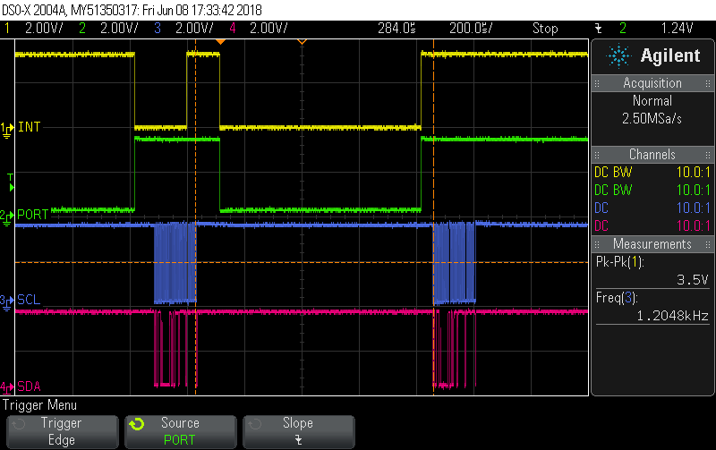
    Tried manual reading after INT pin getting into the state, its remain de-asserted. Please find the scope capture. This case rises when port status is getting changed during I2C transactions.

    Zoomed Image

    Regards

    Bala

  • Hello Bala, Francis,

    It seems clear now that the TCA9555 is working properly, the problem is in the ISR.  Do you agree?

    The question at hand which the second data read would answer, is to confirm that reading the data port really does clear INT in the observed case that the input port changes during a data transaction.  The scope observation does not answer this question since the data input changes again during the second data transaction.  To answer the question, the data input would have to remain constant (high) through the second transaction.

    Also, as a matter of terminology, them INT is low it is not 'de-asserted', or negated, it is asserted.  That INT low signals interrupt.

  • Hello Matthew,

    matthew reich said:
    It seems clear now that the TCA9555 is working properly, the problem is in the ISR.  Do you agree?

    No. Look at the another scope capture. Processor missed to read the second interrupt but INT pin is going to high state when there is change in Port status  irrespective of I2C read as per the datasheet suggestion.

    The problematic situation arises when Port change the state when the data transaction on the I2C bus.

    Regards

    Bala

  • Hello Bala,

    I think some of the confusion is coming on how the INT is toggled.  I have attached the simplified schematic that controls the INT pin.  Note that the INT pin is controlled by an XOR, which means that it if their is a difference between Q and the IO pin it will turn on the gate of a FET to pull the nINT pin low.   If both are high or both are low then the INT is not asserted (LOW). 

    This means that if an IO changes state before a read then the interrupt is asserts (pulls the INT pin low) .  It also means that if the IO pin returns to its original state the INT be we be de-asserted assuming a read hasn't occurred (INT is released and gets pulled high via pull-up resistor).  The waveform you showed is showing the part working properly. 

    -Francis Houde

  • Hello Bala,

    The scope picture shows correct TCA9555 operation.

    Here is the sequence of events:

    INT H, PORT L, no transaction: initial state. INT negated

    INT L, PORT H, no transaction : Port change in state causes internal data which is L to be unequal to input data, causing INT asserted.

    INT H, PORT H, transaction: Prior INT assertion triggered ISR, which scheduled data transaction.  Transaction samples the port data, changing the internal data to H, matching the port data, causing INT negated.

    INT L, PORT L, no transaction: Port change in state causes internal data which is H to be unequal to input data, causing INT asserted.

    INT H, PORT H, no transaction: Port change in state causes internal data which is H to be equal to input data, causing INT negated.

    INT H, PORT H, transaction:  Prior INT assertion triggered ISR, which scheduled data transaction.  Transaction samples the port data, which keeps the internal data at H, matching the port data, causing INT to remain negated.

    There is NO PROBLEM in this sequence.