This thread has been locked.

If you have a related question, please click the "Ask a related question" button in the top right corner. The newly created question will be automatically linked to this question.

DS90UB953-Q1: connecting two 953 serializers to one 954 deserializer

Expert 6460 points
Part Number: DS90UB953-Q1

Dear Team,

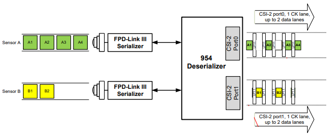
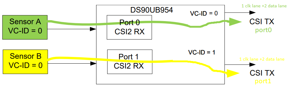
our customer needs to connect two 953 serializers to the 954 deserializer. One 953(0) is connected to RIN0 and other 953(1) is connected to RIN1.

And then we want that the picture from:

  • RIN0 goes to  2LANE mipi port 0 : CSI_CLK0_PN, CSI_D0_PN, CSI_D1_PN
  • RIN1 goes to 2LANE mipi port 1 :  CSI_CLK1_PN, CSI_D2_PN, CSI_D2_PN.

How can we do this scenario?

Thanks for your help,

Customer

  • Hi Bartosz,

    Are you currently using the 953/954 EVMs to test your setup?

    Regards,
    Jonny
  • Hello,
    They can use the virtual channels in 954 to achieve this. The virtual channels are part of the MIPI CSI-2 specification, the 954 would pass through the VC ID's to the other side.

    Please refer to the DS90UB954 datasheet section 7.4.20 for additional information on VC mapping.
  • Hello,

    the datasheet is known to us. 

    Can you indicate how do we have to set the register and which register to achieve the following:

    a)

    Sensor A ( VC-ID = 0) remaps to VC-ID =0  ( uses RX0 [pin 41,42])

    Sensor B ( VC-ID = 0) remaps to VC-ID =1  ( uses RX1 [pin 32,33])

    b) 

    the image from Sensor A is only present on CSI TX port0 (pin for clk (12,11) pin for data0 (14,13) pin for data1 (16,15))

    the image from Sensor B is only present on CSI TX port1 (pin for clk (19,18) pin for data0 (22,21) pin for data1 (24,23))


    Here is the picture of what we want to do :


    In the documentation of DS90UB960 the quad de-ser there is register FWD_CTL1(0x20) and the bits [0:3] are mapping the input RX port to CSI-2 port:

    Thanks for your help.

  • Hello Bartosz,


    This configuration is not possible using the 954. To achieve this kind of solution you have two options:


    1- Use the replication mode as described in the Datasheet. You will be getting the data of both cameras on both CSI outputs. By using different Virtual Channel IDs, you can separate each camera stream in your Processor.


    2- To use the 960 instead of the 954. The 960 supports natively 4 inputs and 2 outputs. There it is possible to get camera 1 stream into CSI output 1 and camera2 stream into CSI output2.


    Kind Regards,

    Hamzeh