This thread has been locked.

If you have a related question, please click the "Ask a related question" button in the top right corner. The newly created question will be automatically linked to this question.

TPS2546: Problem Charging Samsung S8+

Part Number: TPS2546


Our board based on the TPS2546 is not charging a Samsung S8+.  The eval board is able to charge the same phone when configured in a similar way.  I am working through the difference but have not had any luck.  Other devices (iPhones, iPads, Samsung Galaxy Tab E, ASUS Memo Pad, Topelotek) are charging just fine. 

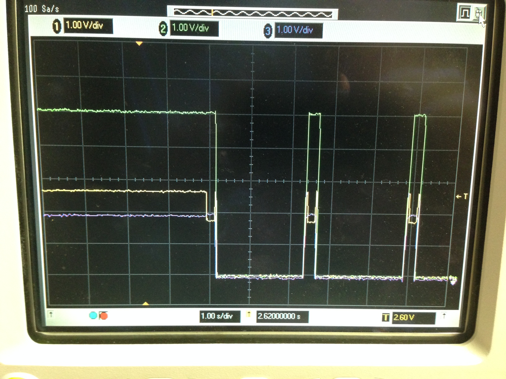
When the phone is connected to our board, the D- line is pulsing every 2.5s with the following: 2.7V for 48ms, 2.0V for 200ms, 2.7V for 32ms, and 0V until the next pulse.  During this pulse the Vbus is turn on and the D+ is asserted at 2.0V. 

I have attached my schematic for review. 

Charger.pdf

  • Hello Wayne,

    Try changing the connection to ILIM_SEL from a value of 0 to a value of 1. Let me know how that effects your system. Can you also include a screen capture of the oscilloscope while the error is occurring.
  • I have tested the TPS2546EVM eval board with the ILIM_SEL set to low and high.  It is able to charge the Samsung S8+ in either configuration.  I have not directly tested our design with the ILIM_SEL set to 1.  Let me know if there is a specific need to test this on our design.

    Attached are two wave forms.  The first waveform shows D- on channel 1 and Vbus on channel 2.  The second shows D- on channel 1 and D+ on channel 2. 

    Wayne

  • Attached are two more screen shots from the o-scope.  These are shots of the startup sequence when the phone is connected to the charger.  Channel one is D-, channel 2 is Vbus, and channel 3 is D+.  The first image is of the eval board.  The second image is of our design. 

    Another question... Can you decipher or provide me with a decoder ring for the IC markings?

    The eval board has these markings.
       2546
       TI 4AF
       S14V

    Our design has these markings.
       2546
       TI 718
       A51L

    Thanks for the help.

    Wayne

  • I believe I have found the source of my problem.  The Samsung S8+ appears to be back driving the Vbus causing the voltage to rise above 5V.  We are using an LMS3635 to generate the 5V rail for our design.  It appears to be detecting the 5.3V and asserting its Reset output flag.  We have the Reset connected to the Enable of the TPS2546 Charger chip.  The Reset pulse causes the USB charger to disable and restart negotiations with the phone. 

    The easy solution is to sever the connection between the LMS3635 Reset pin and the Enable of the TPS2546.  I have a zero ohm resistor in the design for that purpose.  My goal of connecting these pins together was to ensure a clean power up of the TPS2546 in case of a glitch on the incoming power rail. 

    Do you have any suggestions on how else to protect against glitches and/or back-feeding from the Vbus? 

    Wayne

  • Hello Wayne,

    Apologize for the late response. Just to clarify what is happening, the Reset pin for the LMS3635 is connected to the enable pin for the TPS2546. The LMS3635 detects the output rail to be 5.3V, and asserts the reset flag which disables the TPS2546?

    As far as protection on VBUS, the TPS2546 has two features to protect again over current and under voltage. They are explained in the following sections. The overcurrent is mainly used when there is a short after VBUS while the under voltage is used to help regulate the voltage coming into the TPS2546.

    Let me know if this helps solve your problem or not! If so, please click this resolved my issue

  • Your statement is correct...

    Apologize for the late response. Just to clarify what is happening, the Reset pin for the LMS3635 is connected to the enable pin for the TPS2546. The LMS3635 detects the output rail to be 5.3V, and asserts the reset flag which disables the TPS2546?

    When the TPS2546 is reset and turns off its output, the 5V rail drops to 5V and LMS3635 deasserts its Fault flag.  This allows the TPS2546 to re enable and the process starts over again.

    Testing has found that the design appears to be immune to power glitches when the Fault flag is disconnected to the TPS2546 Enable pin.