This thread has been locked.

If you have a related question, please click the "Ask a related question" button in the top right corner. The newly created question will be automatically linked to this question.

SN65HVD232: SN65HVD232 die every time!

Part Number: SN65HVD232

We have CAN bus with 1 central block and 4 nodes. Each node have STM32 microcontroller and SN65HVD232 transiever.

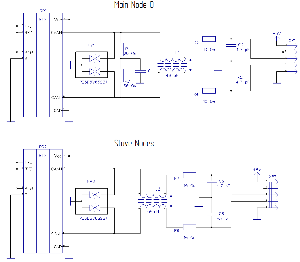
Central block has schematic

4 nodes have schematic

Line length is 2 meters.

Problem: SN65HVD232 chips spontaniously die in any node! Last time 3 of 5 burned! It gives short between +3.3 and GND and whole device shuts down. How is it possible?

SN65HVD232 should be tolerant even for short connection between CANL and CANH. Power supply is stable 3.3V... Help me please.

  • Hello,

    Thank you for your question.

    Can you clarify a few items in your post for me?
    What do you mean by "It gives short between +3.3 and GND"? Is the device physically shorted between VCC and GND? Do you observe high current into the VCC pin or the bus pins?
    Do you have any current measurements for the short condition when the device ceases to operate?

    Does each node have a termination resistor? Typically only two termination resistors are used in a network, one at each end. I just want to make sure that the bus is loaded correctly.

    In your central schematic, what is the purpose of your 5K pull-up and pull-down resistors on CANH and CANL?


    Best Regards,
    Max Megee
  • Yes, SN65HVD232 becomes damadged - short circuit 3v and gnd. Lab power source goes into current limit 500 ma (normal is 4 ma) and SN65HVD232 is hot as hell. After  SN65HVD232 remove device have normal current and works. I can not imagine what happens.

    Resistors were placed by datasheet recomendation

  • All CAN bus works fine for some days, but damage happens absolutely spontanious.
  • R15 and R16 are placed for alignment of CAN bus levels. Without R15, R16 CAN bus works unstable. Termination resistors were placed on every node, so a common resistance is about 25 ohms. But SN65HVD232 should have protection from different circuit errors, even for shorting of CANL and CANH, is not it?

  • On this picture is shown main device and optional one. Optional can be connected to main from time to time, so CAN configuration is a "variable star".

    VD232 burned on main network only. Optional was not tested yet.

    What configuration of is termination resistors should be used for this topology?

  • For your main network, we would recommend termination resistors only for the nodes placed at the furthest ends in the network (node 2 and node 4). With termination resistors placed at every node in order to compensate for reflections, the overall bus loading can increase to the point where each node may not be able to drive enough VOD to pass communication standards. Bus current during communication will also increase. As a general practice, star networks should be avoided. Star networks may induce reflections on the CAN bus that can be fatal to communication.

    Do you know if your network failure and the optional network are connected in any way? The SN65HVD232 should have been able to withstand current limit if the extra loading caused high current, but continuous operation at high current over its lifetime can affect its reliability.

    Regards,
    Max
  • Both networks  should be modular. It means that user can disconnect, for example,  Node2 or Node3 and Node4 or Node6,7,9 etc... and whole device should work.  The length of every wire is no longer, than 0.5 meters. CAN Star connection is described in US5734658A patent of Daimler-Benz

    patents.google.com/.../US5734658

    I think to use only one termination resistor 60 ohms on master side. Is it wrong way?

  • Thank you for the network diagrams and description. I think you should be okay with your split termination as shown on the master node, and one more termination at the Star Node that you labeled.

    I am looking into any more potential causes for the catastrophic failure that you have observed and will get back to you early next week.

    Best Regards,
    Max
  • Overvoltage transients on the VCC pin or bus pins may cause damage to the device. I noticed that your bus pins do have transient protection diodes, so you may have protected yourself from a DC fault. However, a fast transient overvoltage may still have gotten through to the bus pins to damage them. Since you mentioned a 3.3V short to ground, I would be curious to see if you had a surge anomaly on your power supply in any way via hot-plug, etc.
    You could run a curve trace on the CAN pins and the VCC pin to see if there are any characteristics that might point to a root cause of failure. I would be curious how much current these pins draw (and at what voltages), after you observed that they were damaged.

    Best Regards,
    Max
  • CAN wires are located near 100 watt BLDC motors wires, so it could be current outbursts, that generate strong noise voltage in CAN bus.
    I am going to make uncompromising schematic for CAN protection with ESD PESD5V0S2BT (https://assets.nexperia.com/documents/data-sheet/PESD5V0S2BT.pdf

  • And 10 Ohm resistors for overload protection.

    Please, appreciate it and, probably, give some advice.

  • Thank you for the detailed schematics. There are a couple of things that you might want to watch out for.
    1. The ESD diodes that you have chosen for the CANH/CANL lines are rated with a 5.5-9V breakdown voltage. This could potentially cause a problem if there are any ground shifts in your network and the CANH/CANL lines shift higher than 5V from ground. In this case you may see an unwanted engagement of the ESD diode, effectively creating a bus short to ground.

    2. The 10-ohm resistors that you have included in series on the CAN bus have the potential to significantly impact the signal amplitude on the bus lines (up to a 30% loss when terminated with 60-ohm load resistors). You may want to consider their impact on signal integrity over the whole system if you choose to implement them.

    Best,
    Max