This thread has been locked.

If you have a related question, please click the "Ask a related question" button in the top right corner. The newly created question will be automatically linked to this question.

ISO1050: one bad device will break other devices on the same CAN BUS

Part Number: ISO1050
Other Parts Discussed in Thread: SN6501

Hi,

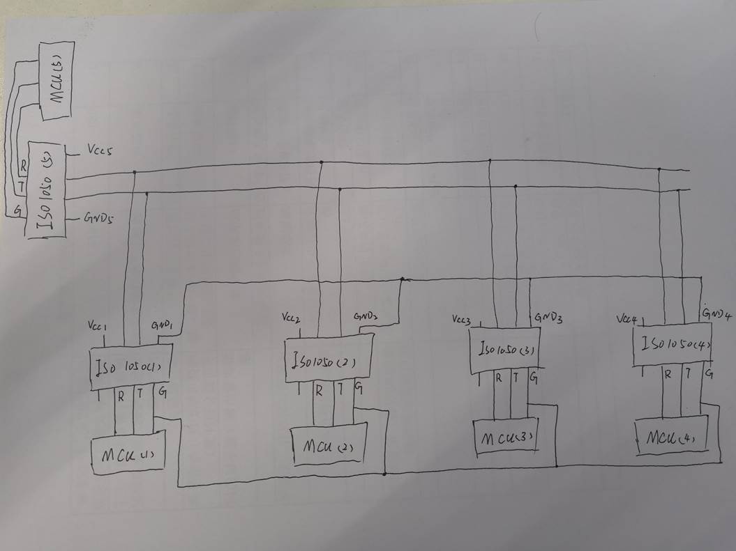
my customer is using our ISO1050 to communicate between one master and four slaves. The four slaves GND are connected together, isolated from the master. The 5 ISO1050 CANH and CANL are connected together.

There is a time that the four ISO1050 of slaves are broken, but the master's ISO1050 is good. The broken part behaves CANH, CANL are shorted to GND2(about 10ohm), and by measuring the diode voltage drop with multimeter, the drop from CANH to VCC2, CANL to VCC2, GND2 to VCC2 are 0.5V.

Then they replace the ISO1050 of 3 slaves. Each slave can communicate with the master. Then they connect one bad slave, 3 good slave, one good master together,

all of the slaves can't communicate with the master. Then they found that all the 3 new ISO1050 are broken again. The same behavior as I described before.

They customer's main concern is why the broken device can cause the good device on the same CAN bus break.

  • Hi Howard,

    Thank you for posting your question on E2E. I will be happy to work with you and help you out here.

    Reading through the description, there could be a few different things that could be going wrong. To help us debug this quickly I have written down a few questions, getting clarifications would be great:

    1) can you please post a simplified block diagram of the setup, including how the power supply and isolated power supplies are setup? Is the CAN bus network terminated?

    2) As you already know, the ISO1050 provides galvanic isolation built-in from the left side (MCU interface, Vcc1, Gnd1, TX, RX) to the right side (CAN bus side, Vcc2, Gnd2, CANH, CANL etc). So if the 4 slaves are isolated from the master (need to see how this is done please), but if all five CANH, CANL are connected together, then the master is not really isolated from the slave, since they are all in the Vcc2<>Gnd2 domain.

    3) It is possible that the isolation maybe unintentionally getting bypassed and causing shorts, and creating damage so that is why it is good to align on the setup to make sure.

    4)  CANH, CANL impedance w.r.t GND2 being 10ohms  and having (Vcc2-CANH) = (Vcc2 - CANL) = (Vcc2- GND2) = 0.5V means the parts are getting over-stressed (biasing).  On a healthy part, CANH impedance to Vcc2  =  CANL impedance to GND2 = Rid spec in the datasheet = 30k to 80k-ohms  (in default recessive state)

    5) How are these parts driven? Is it from MCU? Clock signal or DC? If they are all trying to drive a dominant  (TXD = low) at the same time for an extended period of time, it may cause communication issues as well. 

    After we analyze and align on the setup , the next step would be to start afresh with 5 known good devices. And try the communication with one master and one slave at a time. 

    Best regards,

    Abhi

  • Hi,

    please see the picture below.

    The GND2 of four slave's ISO1050 are connected together, but they are all isolated with each other since the VCC2 of these four ISO1050 are from isolated power supply.

    By replacing all 5 ISO1050, it's able to communicate correctly.

  • Hi Howard,

    Thanks for posting the follow-up.

    So with the connection above, each MCU is only isolated from its own CAN bus.

    • All the MCU inputs (TX, RX, Vcc1, GND1) on the different ISO1050s are on the same domain as each other (Domain 1 = Vcc1 <> Gnd1 of each ISO1050)
    • Similarly, all the CAN side pins are connected to each other (CANH, CANL, VCC2, GND2) of each ISO1050 are connected to each other and so are also in the same domain (Domain 2, Vcc2<>GNd2 of each ISO1050)

    It is possible that damage on one device  would create an extended short circuit on the other pins on the bus, since that part is shared. Also any EOS/ESD event on the CAN bus can affect multiple devices because the CAN lines on all 5 devices are all connected together.  [Isolation will only isolate the MCU side to the CAN side]. so this maybe why you were seeing the symptoms earlier.

    It is good to hear that all five devices are able to communicate clearly now. Is it correct to state that the issue is now gone?

    For completeness. how is the isolated power supply being generated ? Is through SN6501/SN6505 based solution?

    Please let us know if there any other questions. 

    Thanks,

    Abhi

  • Hi,
    each ISO1050's isolated power supply is from an isolated flyback power, so they should be all isolated. But the four slave's ISO1050's GND2 are connected together so that they are finally not isolated.
    The customer's concern is the phenomenon that "one failed unit will cause other units fail".
    They wonder if the phenomenon is inevitable or there may be any chance for them to change the circuit to eliminate the possibility of the phenomenon happens.

  • Hi Howard,

    Understood.  Yes, this phenomenon can indeed occur, but we can also take some steps to mitigate this.

    • For example,  system level over -voltage events (greater than the Abs max ratings of the datasheet) on the CAN bus can cause damage to multiple units, since the CAN lines are interconnected. 
      • So for that, TVS diodes are used to protect the CAN pins from over-voltage (please see this E2E link for recommendations) . 
    • It is normal to see Common mode Chokes (CMC) being inserted in series with each CAN line to improve EMC (this is optional and depends on the customer needs). 
    • Also, it is recommended to use a power supply with built in current limit. The ISO1050 also has built in current limit protection on the CAN lines (not the whole chip but just on the CAN pins).  All of these steps combined will improve system robustness.
    • Of course, the ISO barrier will also help shield/isolate the MCU from high voltages on the CAN bus and also provide ground loop isolation.

    Hope this helps! Please feel free to let us know if you have further questions.

    Thanks,

    abhi

  • Hi,
    since it's the four slave's ISO1050 broke, so will it help if we isolate the GND2 of the four ISO1050?
    Besides, could you give an example of how one broke ISO1050 will bring other devices broke? I'm still not quite sure about it.
  • Hi Howard,

    1) Isolating the GND2s of the four slaves will help provide another layer of protection. So if there is a spike on one of the suplies/grounds, the others will not be directly affected. ( since they will be generated independently)

    2)  Propagation of fails. This is where we really need to understand the end customer's observations of 'fail' in more detail. There are two sets of scenarios here: functional fails and  damage fails .

    Example for functional fail on one device causing fail on others: This can be true in general , not just for any one CAN chip. This can also be more common.  Let us say CANH on one unit somehow has a dead short to Vcc and CANL to GND. Then this device will always be  stuck in dominant state ( Vod > 1.5V) and totally disrupt other communications, until there is a dominant time out (DTO). Even after a DTO, this node will be tried to put back into recessive, but because the lines are shorted and stuck, it will continue to fail and be stuck.   Because the CAN nodes are interconnected to each other, the other lines will also see this and so the communication on the bus on other devices also will fail. You can have  more similar scenarios, when CANH is shorted to CANL (stuck recessive, Vid = 0), or CANL is shorted to Vcc (Vod  < 0, so again it will be always be recessive etc). All of these will result in communication fail on a device causing the communications on other devices to also fail.

    The damage fail case is more tricky. Because the CAN lines are connected together to each other, it is more likely that an EOS event on the CAN bus can cause damage to all of them at approximately the same time. It may look like one unit is causing the others, but it really more likely that they came from the same EOS source (ESD, EFT etc.). One example case maybe that if the node spacing on the CAN cable is not uniform, then that could result in different prop delays from the same EOS source to the different units.  Other than this, it is very difficult and requires a lot of unlikely events to happen together for unit to damage another unit. 

    Hope this clarifies.

    Best regards,

    Abhi