This thread has been locked.

If you have a related question, please click the "Ask a related question" button in the top right corner. The newly created question will be automatically linked to this question.

SN65DSI85: Horizontal and vertical sync error on Sn65DSI85

Part Number: SN65DSI85
Other Parts Discussed in Thread: SN65DSI83

Hello Team,

We are configuring our LVDS panel using bridge chip sn65dsi85. The panel timing parameter is not standard, please see the below timing parameter.
Pclk - 152.15, HPW-32, HBPR-32, Hactive-1920, HFPR-8, VSW-3, VBPR-158, Vactive- 1080, VFPR-32

We have generated the register settings for sn65dsi85 from DSI tuner but it did not worked for us. Please see the attached file "D2L_152.1501". We changed certain parameter defining the porch values and made a new setting which is also attached as "152_15_d2l.txt".

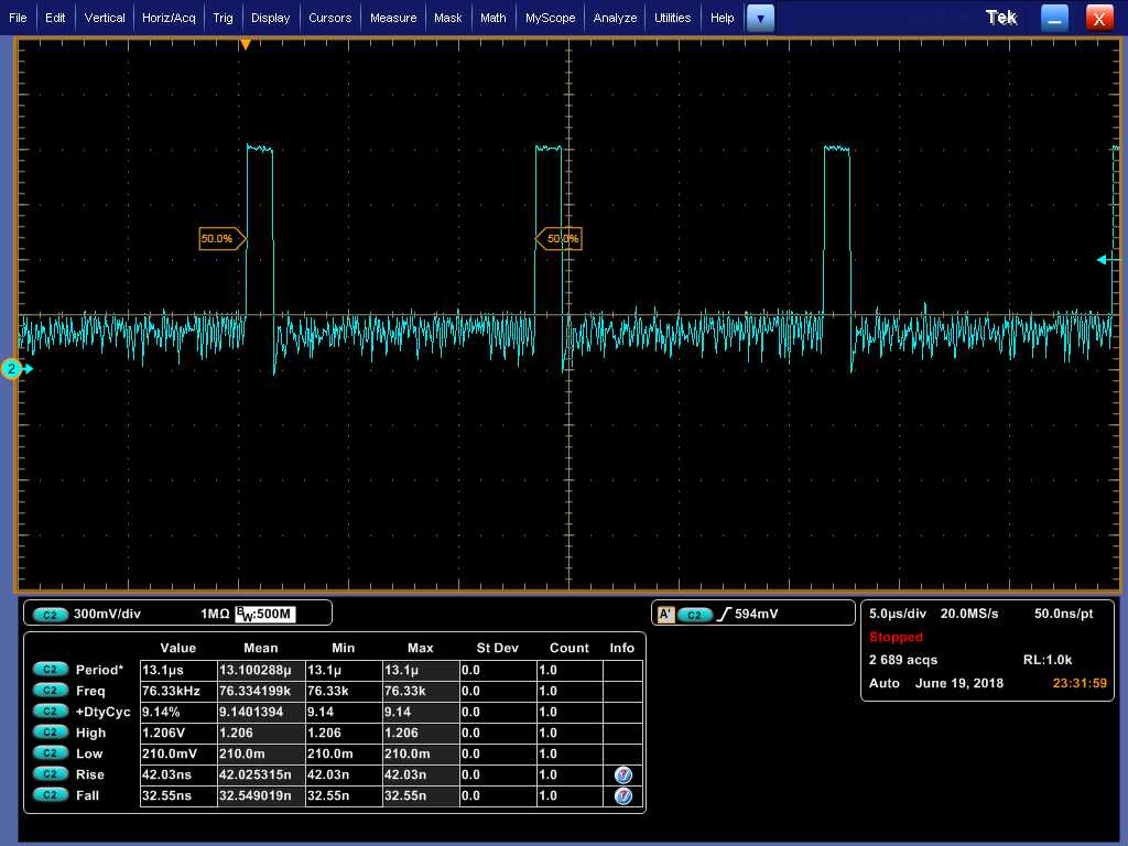
While reading the error registers E5 and E6 we are get the value 81 and 80, which are the HS and VS error.
Can you please help us resolve this issue.

Thanks.

//=====================================================================
// Filename   : D2L_152.1501.txt
//
//   (C) Copyright 2013 by Texas Instruments Incorporated.
//   All rights reserved.
//
//=====================================================================
0x09              0x00
0x0A              0x0b
0x0B              0x10
0x0D              0x00
0x10              0x40
0x11              0x00
0x12              0x5b
0x13              0x5b
0x18              0x6c
0x19              0x00
0x1A              0x03
0x1B              0x00
0x20              0x80
0x21              0x07
0x22              0x80
0x23              0x07
0x24              0x00
0x25              0x00
0x26              0x00
0x27              0x00
0x28              0x21
0x29              0x00
0x2A              0x21
0x2B              0x00
0x2C              0x20
0x2D              0x00
0x2E              0x20
0x2F              0x00
0x30              0x03
0x31              0x00
0x32              0x03
0x33              0x00
0x34              0x20
0x35              0x20
0x36              0x00
0x37              0x00
0x38              0x00
0x39              0x00
0x3A              0x00
0x3B              0x00
0x3C              0x00
0x3D              0x00
0x3E              0x00


The PLL_EN bit and SOFT_RESET bit are not set as they need to be set per the recommended sequence defined in the datasheet
I2C 1 1 2C 09 1 00
I2C 1 1 2C 0A 1 0B
I2C 1 1 2C 0B 1 10
I2C 1 1 2C 0D 1 00
I2C 1 1 2C 10 1 40
I2C 1 1 2C 11 1 00
I2C 1 1 2C 12 1 5B
I2C 1 1 2C 13 1 5B 
I2C 1 1 2C 18 1 0C
I2C 1 1 2C 19 1 0F
I2C 1 1 2C 1A 1 00
I2C 1 1 2C 1B 1 33
I2C 1 1 2C 20 1 80
I2C 1 1 2C 21 1 07
I2C 1 1 2C 22 1 80
I2C 1 1 2C 23 1 07
I2C 1 1 2C 24 1 38
I2C 1 1 2C 25 1 04 
I2C 1 1 2C 26 1 38 
I2C 1 1 2C 27 1 04 
I2C 1 1 2C 28 1 32
I2C 1 1 2C 29 1 00
I2C 1 1 2C 2A 1 32
I2C 1 1 2C 2B 1 00
I2C 1 1 2C 2C 1 20 
I2C 1 1 2C 2D 1 00
I2C 1 1 2C 2E 1 20
I2C 1 1 2C 2F 1 00
I2C 1 1 2C 30 1 03 
I2C 1 1 2C 31 1 00
I2C 1 1 2C 32 1 03
I2C 1 1 2C 33 1 00
I2C 1 1 2C 34 1 20 
I2C 1 1 2C 35 1 20
I2C 1 1 2C 36 1 9E
I2C 1 1 2C 37 1 9E
I2C 1 1 2C 38 1 08
I2C 1 1 2C 39 1 08
I2C 1 1 2C 3A 1 20
I2C 1 1 2C 3B 1 20
I2C 1 1 2C 3C 1 00 
I2C 1 1 2C 3D 1 00
I2C 1 1 2C 3E 1 00
I2C 1 1 2C 0D 1 01
I2C 1 1 2C 0E 1 01

  • Hi Maumita,

    Can you provide the .dsi file that was used to generate the register settings? Also, can you please clear register E5 and E6 by writing 0xFF to both of them before reading them? Some bits may get incorrectly set during the initialization sequence, so they need to be cleared before reading.

    Regards,
    I.K.
  • NonStdPorch_D2LConfig.zipHello,

    Please find the attached .dsi file, while generating these settings the porch values registers remain 0 even after adding porch values.

    We have cleared the register by writing 0xFF but still we are getting the same error mentioned above.

    What exactly does it mean by Hsync  and Vsync error? As we checked the DSI input which worked fine for us.

    Regards,

    Maumita

  • Hi Maumita,

    Firstly, can you have the customer implement the below initialization sequence and see if it resolves the issue?

    1

    Power on

    2

    CLK set to HS and  DATA set LP11

    3

    Set EN pin to Low 


    Wait 10 ms

    4

    Tie EN pin to High


    Wait 10 ms

    5               

    Transfer all register settings

    6               

    Set PLL EN register 0x0D to 0x01 to enable PLL


    Wait 10 ms

    7               

    SW Reset


    Wait 10 ms

    8               

    Change DATA to HS

    I will check the .dsi file tomorrow. If the above doesn't resolve the issue then the next mostly likely issue is a line time mismatch between the LVDS output and the DSI input.

    Regards,

    I.K.

  • Hello,

    Did you got the chance to look into the .dsi file we have shared.
    We checked the sequence provide above but it did not help us, still we are not getting any data on sn65dsi85 LVDS out.

    Thanks.
  • Hi Maumita,

    The .dsi file seems fine.

    1. Can you try enabling the test pattern? This will help isolate the issue.

    2. Can you share a screenshot of the DSI_CLK? Since you're getting a PLL_UNLOCK error it's possible the DSI side has signal integrity issues.

    3. Can you share the panel datasheet? You can email it to i-anyiam@ti.com if you don't want to post it here.

    4. Can you check the line time on the DSI side? The line time (horizontal sync to the next horizontal sync timing from the APU) on the input is preserved when outputting onto the LVDS interface. If the line time is different from what is calculated by the tool, this will cause issues. Even if the DSI source is outputting streams in a burst manner, it is important for the DSI source to fill in the rest of the line time with blanking packets (or LP11) to meet the line time requirement. The line time should be 13.092us.

    Regards,
    I.K.
  •   Hello,

    Please see my answers below:

    1. Yes I tried the test pattern and it works fine for us.

    2. Please see the attached image fro DSI clock.

    3. We cannot share the datasheet of the panel as it not out in the market till now, Please let me know your query over the panel, I will try to let you know all the answers.

    4. Please see the attached DSI waveform of DSI data for line time.

    Thanks.

  • Hi Maumita,

    Can you confirm that you're just getting the sync error on CHA and CHB after clearing 0xE5, and not the PLL_UNLOCK error? Your issue is starting to sound similar to this thread: e2e.ti.com/.../2525665

    Can you try their solution?

    Regards,
    I.K.

  • Hi Maumita,

    I just realized that the other e2e post I referenced was for the SN65DSI83 and is not applicable here since the reserved bits in register 0x10 are actually used here.

    Are you able to confirm my other question though? Are you still getting the PLL_UNLOCK errors or just the sync errors?

    Regards,
    I.K.
  • Hello,

    Even after clearing the registers E5 and E6 with 0xFF, I am getting its values as 0x81 and 0x80. Is their anything which we can modify to solve this.

    Regards,

    Maumita

  • Hi Maumita,

    Since you are still getting the PLL_UNLOCK error it leads me to believe that there are signal integrity issues with the DSI_CLK.

    Can you double-check that it's within specification of what's listed in the datasheet? For example, from the screenshot you provided it looks like the differential voltage is out of spec.

    Regards,

    I.K. 

  • Hi Maumita,

    Any updates on your issue?

    Regards,
    I.K.
  • Hi Maumita,

    Please update this thread if you continue to have issues. For now I will mark it as resolved.

    Regards,
    I.K.