This thread has been locked.

If you have a related question, please click the "Ask a related question" button in the top right corner. The newly created question will be automatically linked to this question.

SN65HVD234: EMI Performance

Part Number: SN65HVD234
Other Parts Discussed in Thread: TCAN334

Dear Team,

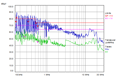
our customer has problems passing the EN55014 spec / ‘Conducted disturbance additional terminals’.

The HVD234 is above the peak spec for lower frequencies (< 1MHz).

Changing the slope resistor did not help on the setup.

Do you have some guidance what the customer can check & try to improve EMI performance?

Thanks and best regards
Martin

P.S.: Please check the link shared offline / comment field

  • Hi Martin,

    The most common approach for improving emissions on a CAN bus is to use a common mode choke on the CANH/CANL lines. Another (less effective but simpler) approach is to modify the termination to split it into two series resistances (each half the termination impedance) with a shunt capacitor to ground at the center point for filtering. Filtering is also possible via capacitances directly on the CANH and CANL lines, but the values that can be used there are limited since this will start to reduce the achievable signaling rate on the bus.

    Have you tried any of these approaches so far?

    Are emissions being measured solely on the CAN lines, or are you looking at power lines as well? If looking at power lines, filtering elements like ferrite beads on those can be beneficial, although unfortunately most of their benefit is above 1 MHz.

    It can also be good to confirm the source of the emissions by correlating the frequency peaks to different system components. Just to confirm - do the observed peaks correspond to harmonics of the CAN data rate?

    Max
  • Max,
    thanks a lot for your answer.

    Yes, the customer confirmed that they tried the middle split termination as well as the CMC. Nothing helped so far.
    They see the emissions only on the CAN line and not on the power lines.

    Please see below the EMI diagram:

    Concrete question from the customer:

    * To what level of capacitor filtering directly on the CAN-bus signals is allowed, what is the required step-response for CAN-bus to remain functioning?

    Thanks and best regards
    Martin

  • Martin,

    It's a bit hard to give a direct answer on the capacitance. Values in the 60-100 pF (per node) range are common, and higher values are sometimes used as well if the data rates or number of nodes are lower. The thing to keep in mind is that although the recessive-to-dominant transition is relatively strongly driven by the CAN transceiver, the dominant-to-recessive transition is only weakly biased and therefore the transition time is a function of the RC decay of the bus. As the bus capacitance increases, this dominant-to-recessive edge is slowed disproportionately, and the net result is a distortion of the bit durations seen by the CAN controller (via the RXD line). The amount of distortion that is allowable depends then on the timing margin of this interface (which would depend on things like the sampling rate of the controller, where within the bit period the sampling point is configured, etc.).

    One EMC-related challenge that this device presents is the mismatch in common-mode level between dominant and recessive states. Typically CAN transceivers set the recessive level voltages on CANH/CANL to VCC/2 so that the common mode component of the signal (average of both lines) remains consist between both states. This device sets the recessive level to 2.3 V, though, which is similar to what would typically be used on a network powered by 5-V CAN transceivers. This means that the signaling will not be totally balanced, and as the device transmits data there will be both a differential-mode component as well as a common-mode components (which would likely show up on a conducted emissions test such as this).

    Does this network contain only 3.3-V transceivers? If so then a solution may be to externally bias the recessive-state common mode to 1.65 V (VCC/2) by using a resistive network. Or, a 3.3-V device with a centered recessive bias like TCAN334 could be used. If a mixture of 3.3-V and 5-V transceivers are used you could experiment with finding a bias point between 1.65 V and 2.5 V. This wouldn't be optimal for either type of transceiver, but if the emissions profile of the network when the 5-V transceivers are active is passing the limit then maybe it makes sense to trade off some degradation there for improvement in the 3.3-V transceiver performance.

    Max