This thread has been locked.

If you have a related question, please click the "Ask a related question" button in the top right corner. The newly created question will be automatically linked to this question.

PCA9306: pull up resistor problem

Part Number: PCA9306

Hi, 

My customer is using PCA9306DCUR  for the I2C of HDMI, voltage level is 1.8V and 3.3V. now is having problem of pull-up resistor selection.

When following the selection guide from : 

http://www.ti.com/lit/an/slva689/slva689.pdf

condition: 

The result is : 900 ohm to 2.95Kohm, selecting the 2.2K. 

After using this resistor value, some of the monitor will not work and some will. 

This problem become better after increasing the pull up resistor up to 4.7k to 100K ohm. 

May I ask if there are other things need to be consider on this case?  

Thanks for your help. 

  • Hi,

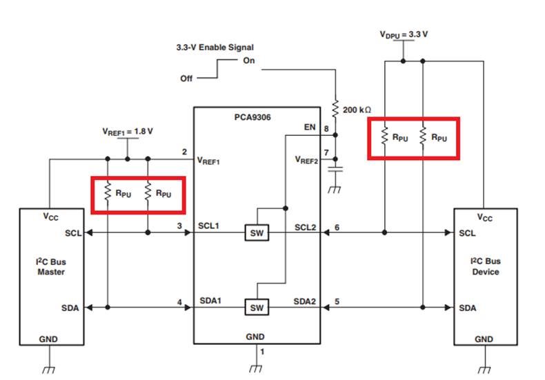
    These calculations are accurate for a single I2C bus and if both buses were isolated (using a buffer for instance), this would be correct. However, the PCA9306 uses a pass-FET method to propagate lows across the device. When this happens, the buses are no longer isolated and the pull-up resistors on either side now act in parallel. The result is a voltage divider between pull up resistors in parallel (Req = 1.1k in this case) and the pull down FET of the I2C device. This is why increasing the values gave better results.

    The result of some of the monitors working while others failed is most likely due to small variances in the resistors and pull-down FETs on the other I2C devices and values resting near the threshold lows for the monitors.

    Regards,
    Eric
  • Hi Eric,

    Can you give us a more clear block of internal structure? 

    This may help us to understand the things you want to explain.

    From my understanding of your reply, we will need 2 times of the pull up resistor value to overcome this problem under this level shift structure, is this correct? 

    Thank you.

  • Hi,

    Your understanding is correct. Because the resistors are in parallel when the device is active, the resistor values have to be doubled to achieve the desired R PU.

    When the device is propagating a LOW, its pass FET switch attempts to short the two buses together so both sides can be pulled LOW. When this occurs, both pullup resistors act in parallel with ground. In the figure below, Rpu1, Rpu2, and Rds_on_master act as a voltage divider. If the pullup resistors are two low, the resulting voltage across Rds_on_master could be higher than Vol and the device does not read a LOW.

    Let me know if you have any more questions.

    Regards,

    Eric