This thread has been locked.

If you have a related question, please click the "Ask a related question" button in the top right corner. The newly created question will be automatically linked to this question.

P82B96: Transmission Side Pin Tolerance on P82B96

Part Number: P82B96

Hi,

We are currently having the following arrangement in the system.

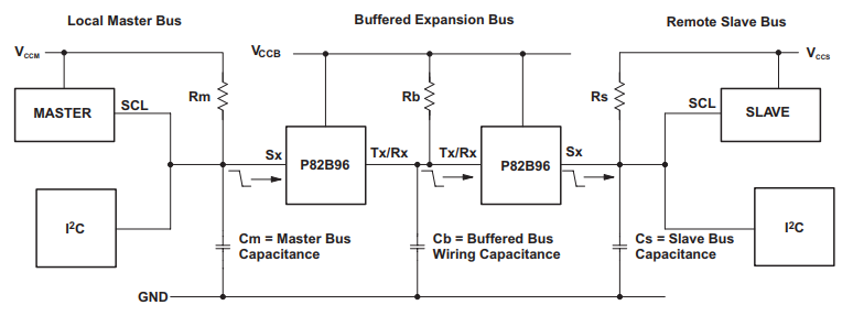
VCCM = 5V , Rm=1.8K , VCCB=5V , RB (Master Side) = 1.8K , RB(Slave Side)=300R , RS=1K , VCCS=3.3V.

We have ESD Protection at both the ends complying to ISO10605.

The transmission side (Tx/Rx) is running length from Master Side to Slave Side is about 3-4 feet. In one of our failure mode, we have observed that the Tx/Rx line getting shorted with 12V which is running very nearby in the harness; which is causing the P82B96 failure. Replacing it with the new part; the system resumed to normal operation.

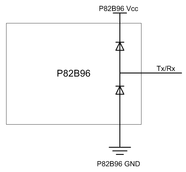
The datasheet section 7.3 mentions the spec of Tx, Ty to be operated/tolerated at max. is 15V. Is this even true when the VCCB=5V? If yes, Why the failure is seen when the lines are getting shorted with 12V?

  • Hello Rushi,

    "Is this even true when the VCCB=5V?"
    Yes, even if VccB is 5V this device should be able to take 12V on Vcc.

    "we have observed that the Tx/Rx line getting shorted with 12V which is running very nearby in the harness; "
    Is the 12V being shorted AT VccB or below Rb connected to Tx/Rx?

    "Why the failure is seen when the lines are getting shorted with 12V?"
    If the short is occuring at the TX/RX pins then there is very little impedance between the pull down FET of the P82B96 and GND.

    -Bobby
  • HI Bobby,

    Thanks for the reply. 

    "Is the 12V being shorted AT VccB or below Rb connected to Tx/Rx?"

    Yes, It got shorted directly on the Tx/Tx (Below Rb and not on VCCB Line). So are you saying that due to the low impedance between GND and FET (being the open drain driver) the overcurrent through it is failing the FET? Datasheet, Section 10.2.4 suggests implementing the Logic Gate circuitry to hold/release the bus lines; will this circuitry still help protect from the direct 12V line short? Else what are the ways?

  • Hello Rushi,

    "So are you saying that due to the low impedance between GND and FET (being the open drain driver) the overcurrent through it is failing the FET?"

    Yes, there is nothing between the FET and the 12V rail to prevent the over current event.

    "Will this circuitry still help protect from the direct 12V line short? Else what are the ways?"

    To me, it seems the easiest solution would to actually just use a series resistor directly in front of the Tx. Tx/Ty can sink a current of 100mA typical therefore if there was a short after Rb and before Tx of 12V then : Rseries = Vshort/IoL(max)

    R series should therefore be atleast 120 ohms. Now this does introduce a potential problem.The Rx of the device looking for the input will see a different output voltage than the Tx of the device sending a signal.

    You can see from the above that one side is generating 131mV but the other side sees 1.68V. In this example, we meet the requirement of ViL of 2.1V (0.42*Vcc) though if you used lower value pull up resistors on Rb or if Rdson/Rseries was larger then the voltage could shift over 2.1V.

    This voltage is essentially a voltage divider: VoL at Rx = (Rseries+Rdson)/(Rseries+Rdson+Rpullupequvilent)*5V

    This example shows we have limited the current into the FET to 92mA when a 12V rail is in direct contact with the Tx rail (after the series resistor).

    Thanks,

    -Bobby

  • Bobby, Understood. Thanks for the detailed explanation.

    But also wanted to check whether in the existing setup (as shown in the first question, w/o series 120R); In such direct 12V short-circuit scenario, does P82B96 has any internal leakage path from Tx to Sx which can introduce high voltage and damage the system side (master/slave) as well?

    Thanks,

    Rushi.

  • Hey Rushi,

    The only 'leakage path' I am aware of should be the internal diodes from GND to the I/O and from the I/O to Vcc.

    Sx and Tx should be high impedance and there should not be any path between those two. I do potentially see the issue of the diode between Tx and Vcc conducting though. If you have the master/slave seeing the same P82B96 Vcc and the power supply can't sink the current then Vcc could deregulate to a higher voltage.

    Thanks,

    -Bobby

  • Thanks, Bobby for all your clarifications. I may come back with more observations after further testing.