This thread has been locked.

If you have a related question, please click the "Ask a related question" button in the top right corner. The newly created question will be automatically linked to this question.

TPS25741: Short 20V Pulse when attaching a USB-Slave

Part Number: TPS25741

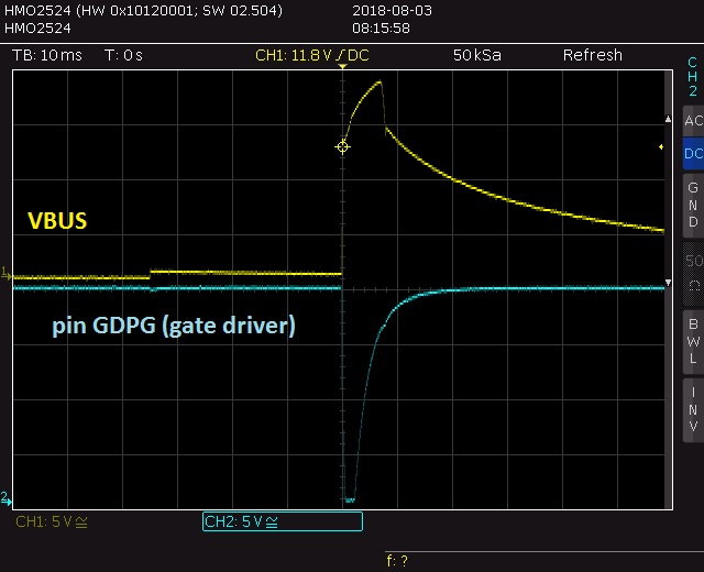
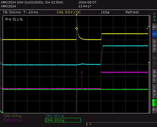
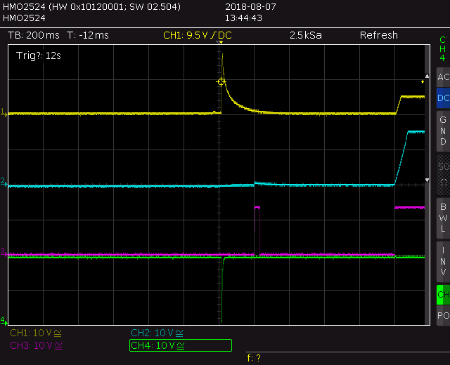
We have our own hardware with the circuit as discribed in Typical Application, data sheet §9.2 "A/C Multiplexing Power Source". We only have 20V instead of 12V. When we attach a USB-C device we see a 10ms long 20V pulse. The voltage then decreases to 0V before rising to 5V. We measure at pin GDPG (gate driver of 20V P-FET) an see a short low level pulse (0V) which enables the 20V FETs. This is long before any communication on CC line starts, it is immediately after connecting the device. Same behaviour is when we only simulate a detach / attach by removing the CC-pull down on the slave. When the resistor is reconnected the 20V pulse appiears.

Any idea why we have this fatal behaviour?

  • Hello Michael,

    Would you be able to share the scope captures of this incident? Also, would you be able to place a current measuring probe to see if there is a large amount of inrush current that is potentially causing the rail to collapse?
  • Hello Adam,

    I think there is a misunderstanding: When I attach a USB-C slave the TPS25741 must not apply more than 5V as long the slave does not request a higher voltage. Otherwise a 5V slave would be destroyed. For example if you connect a Smartphone and the TPS25741 applies - as we see - 20V for 10ms it will be destroyed. Therefore we must prevent the TPS25741 to apply 20V even for 10ms!
  • Michael,

    Correct, VBUS should not rise above 5V unless the sink device specifically asks for it. Just to clarify your issue, you are stating that when your sink device is connected to the TPS25741, the sink device does not request more than 5V, but VBUS goes to 20V for a short period of time?

    Would you be able to send scope captures of this, as well as the schematics for your system?
  • Adam,

    yes, as you see in the capture below the peak comes immediately when we connect the USB-C slave. The picture below with 500ms/div. shows what happens when I disconnect the USB-C cable and reconnect it. I have also attached a detailed capture and a capture of the gate voltage at pin GDPC and the schematic.

  • Hello Michael,

    This is interesting. Would you mind taking another screenshot of the incident? I would like the same time scale as the first screenshot you shared, but instead of VBUS and CC, can you measure VBUS, GDNG, G5V, and GDPG?

    I did not notice anything abnormal about your schematic. The only thing that I did notice is the connection to GD. I cannot see where that connection is going, but make sure that pin is pulled high.

    Also what is the device that you are plugging into the charger replication a sink device? Does this problem persist across all type of sink devices, or is it isolated to a single one?
  • Hello Adam,

    attached are the screenshots (second is only zoomed).  VBUS (yellow), GDNG (blue), G5V (red), and GDPG (green)

  • Hello Adam,

    do you have any news for me? I'm must urgently solve this problem. When attaching an USB stick it is killed by the overvoltage pulse.

    Michael

  • Hi Michael,

    I notice the gate drive circuit for the 19V rail is much different than what we use on the high voltage rail in the TPS23741EVM (it does not directly drive the PFETs). Have you tried using the TPS23741EVM on your system to verify this?

    Regards,
    Darwin
  • Hello Darwin,

    we bought an Evalboard and found the problem (unfortunately it is not solved): at the Evalboard signal /UFP enables the DCDC_5V which enables pin /GD (gate driver enable). As signal /UFP becomes active not before about 200 ms after connecting the USB-C-slave this prevents the gate signal GDPG to become active. I modified the Evalboard in thuch way that DCDC_5V is always active (removing R45 and connected EN-pin of U4 to LDO_OUT) and then I see the same 20V spike on VBUS. I tried to connect /GD to VAUX as shown in the data sheet but this doesn't help as VAUX becomes active too soon (this patch had been easy to do for me). Unfortunately I have 25 prototype boards where /UFP pin is not connected to anything so I can hardly solder a wire to it. The /GD signal is connected to the USB-hub and therefore always enabled (but here I have a series resistor so I could patch something). Do you have any idea?

  • Hi Michael,

    Sorry for the delay as I have been out of office this past week. Any chance to patch a cap with some series resistor (which is already there) to delay the GD signal?
  • Hello Darwin,
    no. My GD signal comes from USB-Hub and is always "on". And the spikes comes every time I connect something to the USB-C connector.