This thread has been locked.

If you have a related question, please click the "Ask a related question" button in the top right corner. The newly created question will be automatically linked to this question.

TPS65986: GPIO Event Map

Guru 29720 points

Part Number: TPS65986

Hi Team,

My customer is designing TPS65986 with Application Customization Tool version 4.01.
Project -> New Project -> TPS65986 -> Standard (Recommended) -> DFP only

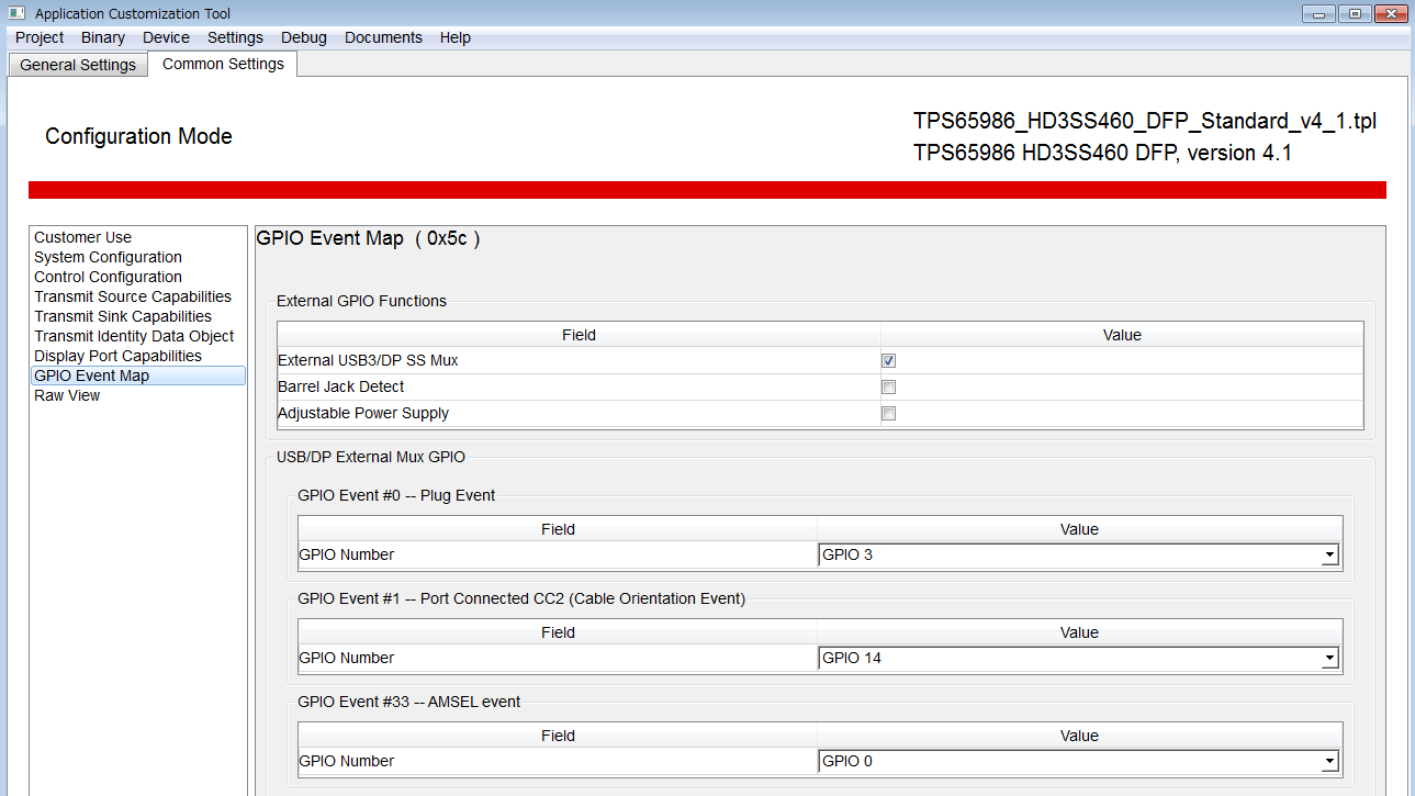
GPIO Event Map in Common Settings shows the folowing.


Is there any way to set push-pull output for any GPIOx?
Is it required to select "Advanced " in selecting project as the following?
Project -> New Project -> TPS65986 -> Advanced -> DFP only

Best Regards,
Yaita / Japan disty

  • Hi Yaita-san,

    The default behavior of our GPIOs is push-pull. In the Advanced templates you have the option of adding the internal pull-up, pull-down, or to set the open-drain output. This is typically not needed. If you use the standard template, your GPIOs will all be push-pull

    If this answers your question, PLEASE select This resolved my issue

    Thank you,
    Eric

  • Hi Eric-san,

    Thank you for your support.

    1)
    I understand GPIO0 outputs low level (Push-pull output) after POR however I couldn't comprehend the following red part.
    (datasheet page 6)

    What does it indicate?

    2)
    I understand there is no way to configure GPIOs if using standard template in Application Customization Tool.
    Is my understanding correct?

    Best Regards,
    Yaita

  • Hi Yaita-san,

    1. The box you highlighted in blue indicates the pin status during a power on reset event. GPIO0 is a special GPIO since it is used to hold a TBT controller in reset during bootup since the TPS65987D and TBT controller can share a SPI-Flash chip. If you are configuring GPIO0 to another GPIO event, you can use it like any other GPIO. Just know that it will be logic low during bootup.

    2. You can configure GPIO Mapped Events using the standard template in the Application Customization Tool. The standard templates only do not support the internal pull-up and pull-down settings which are typically not used.

    If this answers your question, PLEASE select This resolved my issue

    Thank you,

    Eric

  • Hi Eric-san,

    I understand highlighted in blue indicates the pin status during a power on reset event.


    Does "Float pin if it is configured as a push-pull output in the application." indicate the pin shows high-impedance (floating) after power on reset as default?

    Best Regards,
    Yaita

  • Hi Yaita-san,

    Yes, if GPIO0 is configured as "Disabled" it will be High-impedance.

    Thank you,
    Eric
  • Hi Eric-san,

    I think my question is not clear, so let me ask more specific.
    The following screen shows "GPIO Event Map" in standard template.


    If we don't change the setting above, I believe GPIO1 is "push-pull" as you refered.
    >The default behavior of our GPIOs is push-pull.

    1)
    Does GPIO1 outputs low level after power-on(POR) in this case?

    2)
    If my customer don't use GPIO1, should he set GPIO1 to leave floating (not connected) in this case?
    Or should he put 1M ohm pull-down resistor? 


    Best Regards,
    Yaita / Japan disty

  • Hi Yaita-san,

    1. The GPIOs would output low if they are unused.

    2. It is recommended in the datasheet to use a 1M pull-down resistor on GPIO1 if it is unused.

    If this answers your question, PLEASE select This resolved my issue

    Thank you,

    Eric