This thread has been locked.

If you have a related question, please click the "Ask a related question" button in the top right corner. The newly created question will be automatically linked to this question.

SN65HVD233: interfacing two CAN transceivers to make a CAN extender

Part Number: SN65HVD233

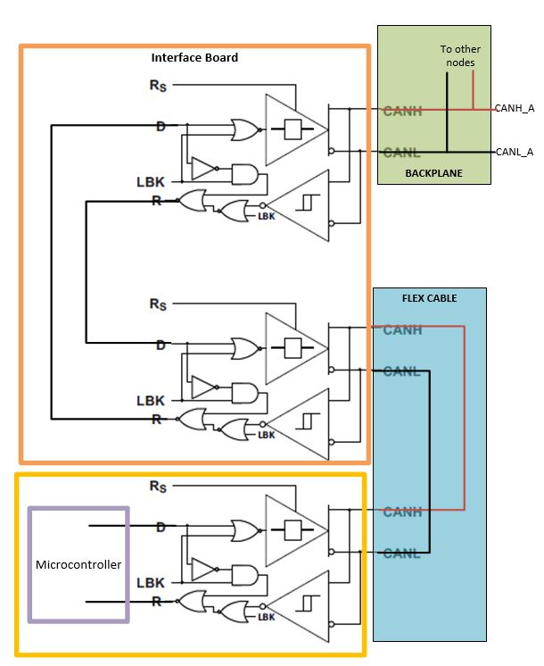
I need a CAN extender chip on an interface board that takes CAN_H and CAN_L signals from CAN BUS A and makes a separate CAN BUS B. I have legacy designs that did this with the AMIS-42700. The AMIS-42700 needs 5V and I don't have easy access to 5V in a new design. I have 3.3V. Creating the 5V on the interface board is difficult for some reasons that I won't go in to. Since I only have 3.3V volts I'm trying to come up with a way to make an extender from two SN65HVD233 chips (or something similar). Would it work to hook two SN65HVD233 the way I have shown below on my interface board?

  • Here's a block diagram:

  • rs,

    In your previous design, was any logic needed between the D and the R pins to stop the devices from getting locked into a dominant state? We have a reference design in development that introduces logic devices between the D and the R terminals so that this case doesn't happen, so I'm surprised to hear you were able to do this with older devices.

    Also, what is the characteristic impedance and length of the flex cable being used?

    Regards,

  • Eric,

    I haven't actually tried what I'm showing on the interface board above. On the previous design we just had the AMIS-42700 hooked up as a CAN bus repeater on the interface board (see diagram below). So that logic would be internal to the AMIS42700. The 5V needed for the AMIS42700 is harder to come by now so I'm looking for a CAN bus repeater that would work at 3.3V instead of 5V. You think there could potentially be some logic needed to prevent latching to a state in the above diagram?

    http://www.onsemi.com/pub/Collateral/AMIS-42700-D.PDF

    The characteristic impedance was ~50 ohms and the flex cable is ~12 inches. There are other CAN nodes on the backplane so we want a CAN bus repeater to prevent the flex cable stub from being present. The flex cable passes through some noisy power switching so we want the CAN to be differential on the flex cable which is why I'm looking for a CAN bus repeater and not just a transceiver.

  • rs,

    Understood, I didn't look up the AMIS42700, I probably should have, that's a pretty nifty device.

    There will be some logic necessary so that a never ending dominant state doesn't occur. Let's label the inputs and outputs D1 and R1, and D2 and R2. The bus on the '1' side goes dominant, causing a 0 to show up on R1 and propagate to D2. This causes the bus on the '2' side to go dominant, and thus R2 has a 0 that goes to D1, and driving a dominant on the '2' side bus as well. Both bus sides will be held dominant and nothing else will be able to transmit through because they're being driven. This doesn't happen in the recessive case because there is no driving, some other node on the bus can drive a dominant even if there were a loop of recessive edges, breaking the cycle.

    The logic implemented in our reference design will stop this constant dominant state from happening. If you check my profile and email me I can send you some files that will help with implementing said logic.

    Regards,
  • Awesome. Thanks!