This thread has been locked.

If you have a related question, please click the "Ask a related question" button in the top right corner. The newly created question will be automatically linked to this question.

DP83867IS: MDIO signal of DP83867IS

Part Number: DP83867IS

Hi!

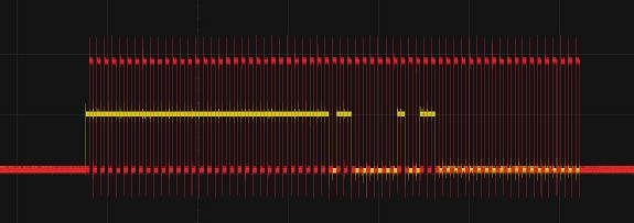
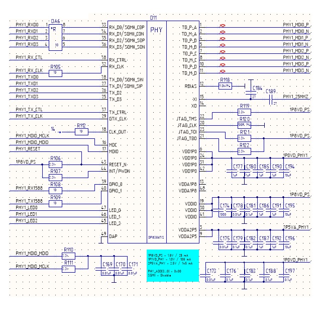
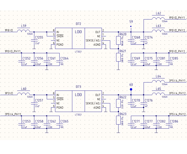
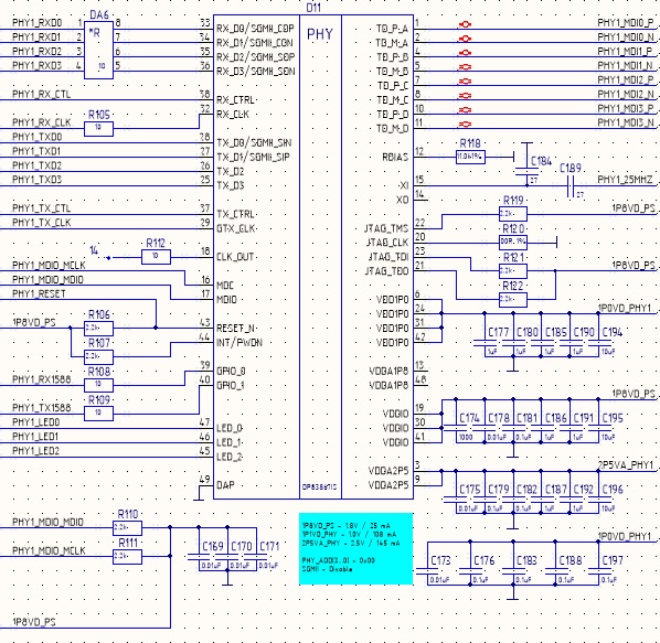
Plese help me. I connect processors system of Zynq-7000 to PHY DP83867IS. Operation mode is RGMII. Power for DP83867IS is tow-supply configuration. The MDIO PHY_ADD configuration is 0x00. MDIO pin have a pullup resistor 2.2 kΩ. When the power is turned on, the MDIO signal is pulled to zero and always reads as zero when reading registers of PHY, but clock is Ok (25MHz). When referring to PHY, the MDIO signal level is ~1.0 V. Then I remove chip PHY signal MDIO is OK.

  • Hi Dmitry,

    Can you send me a schematic?
    Does the Zynq have internal pulls enabled?
    What is the state of JTAG and also all the bootstrap pins?
  • Hi Ross.
    1. In the atachments are my schematic and MDIO line (yellow, ~1V0) + MDC line (red, ~1V8) oscilogram.
    2. Zynq have internal pulls disable.
    3. JTAG: TMS, TDI and TDO pulled up through 2,2kom; CLK pulled down through 100 om.
    4. All bootstrap pins are in mode 1.
    5. My power sequence is VDDA2P5 -> VDDIO (1,8V) -> VDD1P0. VDDA1P8 is unused.

    Best regards,

    Pogorilko Dmitry

  • Hi Dmitry,

    Thank you for the information.
    I believe the issue is that you have no pull-up resistor on MDIO.
    This is an open drain pin.
    Can you enable an internal pull-up on MDIO within the Zynq so that you don't have to add an external one?
  • Hi Ross.

    I'm sorry. Then I cut the part of schematic, I remove the net '1P8VD_PS' for pull-up resistor on MDIO.  In the atachment the correct part of schematic.

    I and my frends make next jab, but to no avail:

    1. Remove R110 and set set pull-up resistor in Zynq. Then all restored.

    2. Remove power from pins 19,30, 41 and set aver pother 1V8 with large delay. Then all restored.

    3. Сhanged the address of PHY to 0x01. Then all restored.

    4. Lowered the level of the clock signal (set C184 to 100pF). In this case, a clock signal is in the pin 18.

    5. The most interesting thing we noticed when forced to do a reset for PHY (pin 43 set to logic 0). During the reset, the PHY releases the MDIO line to 1V8 level.

    Now we conduct experiments with bootstrap pins.

    Best regards,

    Pogorilko Dmitry

  • Hi Dmitry,

    I am a little confused about the above.
    When you say 'then all restored', does that mean the PHY is behaving properly and the potential is at 1.8V?
  • Hi, Ross.

    When I say 'then all restored', that mean the PHY is behaving properly and the potential is at 1.8V.

    Best regards,

    Pogorilko Dmitry

  • Hi Dmitry,

    How was the progress on the different bootstrap configurations?
    Can you take a scope shot of what all the supply rails look like during power-up for a case when MDIO gets pulled to 1.0V and when it is released to 1.8V?
  • Hi, Ross.

    I and my frends solved the problem. I remove resistors R108 and R109 from GPIO pins. After that, the signal 'MDIO' became normal. At the same time, I checked with the programmer that the type of signals in zynq were input without pull-down or pull-up. I still do not understand why the chip PHY behaved this way.

    Best regards,

    Pogorilko Dmitry