This thread has been locked.

If you have a related question, please click the "Ask a related question" button in the top right corner. The newly created question will be automatically linked to this question.

TPS2559: current regulator,

Part Number: TPS2559
Other Parts Discussed in Thread: CSD17578Q3A

Hi sirs,

I 'm designing a driving circuit for VCSEL.  I read 《Illumination Driving for Time-of-Flight (ToF) Camera System》P.14 and found TPS2559 used as current source.

In my case , input voltage is 3.3V,  VCSEL voltage is 2.1-2.5V, 1.6A. So I think TPS2559  is a good choice.

But in practice, output current of  TPS2559 is rising slowly and can't act as a current source.

The trigger signal is 10KHz duty 50%. Series Mosfet with VCSEL is CSD17578Q3A.

Is there any mistake with the application? Or how can I use TPS2559 as a current source ?

  • Hi, Yang,

    TPS2559 is a current limited power switch, there's build in soft start which cause output current rising slowing. This soft start can't be disable and can't be adjusted.

    You can use current limit function to use TPS2559 as a current source. For example, you set the current limit point at 1.6A. If your load is over 1.6A, TSP2559 will limited the current at 1.6A.

    Feel free to ask any questions.

    Regards,
    Bob
  • Hi Bob,

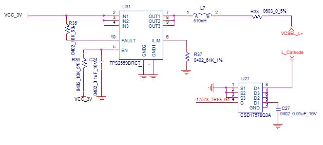
    My circuit is below. It  follows TI's TOF design. Limit current setting is 2A. I place a adjustable resister RL as a VCSEL.  U27's trigger is 10KHz duty 50%.

    I want the current on  RL to be 2A, 10K, 50%.

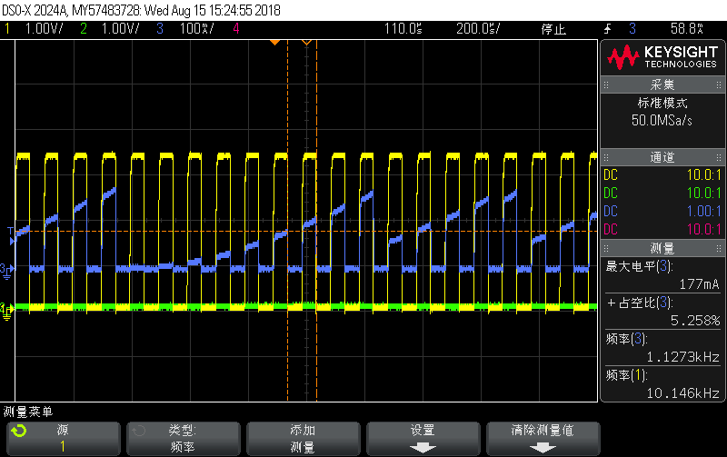
    When RL> 1.5ohm, the output wave is 10K square;

    When RL<1.5ohm, the output wave on RL is nothing but a little periodicity like soft-start's head.

    Can you help me with this problem?

  • Hi, Yang,

    Understood your case.


    Can you please attach the waveform of RL>1.5ohm and RL<1.5ohm.

    Regards,
    Bob

  • Hi, Yang,

    Since I don't get your further question, I will close this thread. Feel free to ask further if any questions.

    Regards,
    Bob
  • Bob,

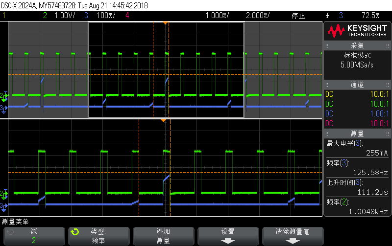
    Sorry to be late. This picture is captured when RL is 1.5ohm. 

  • Hi, Yang,

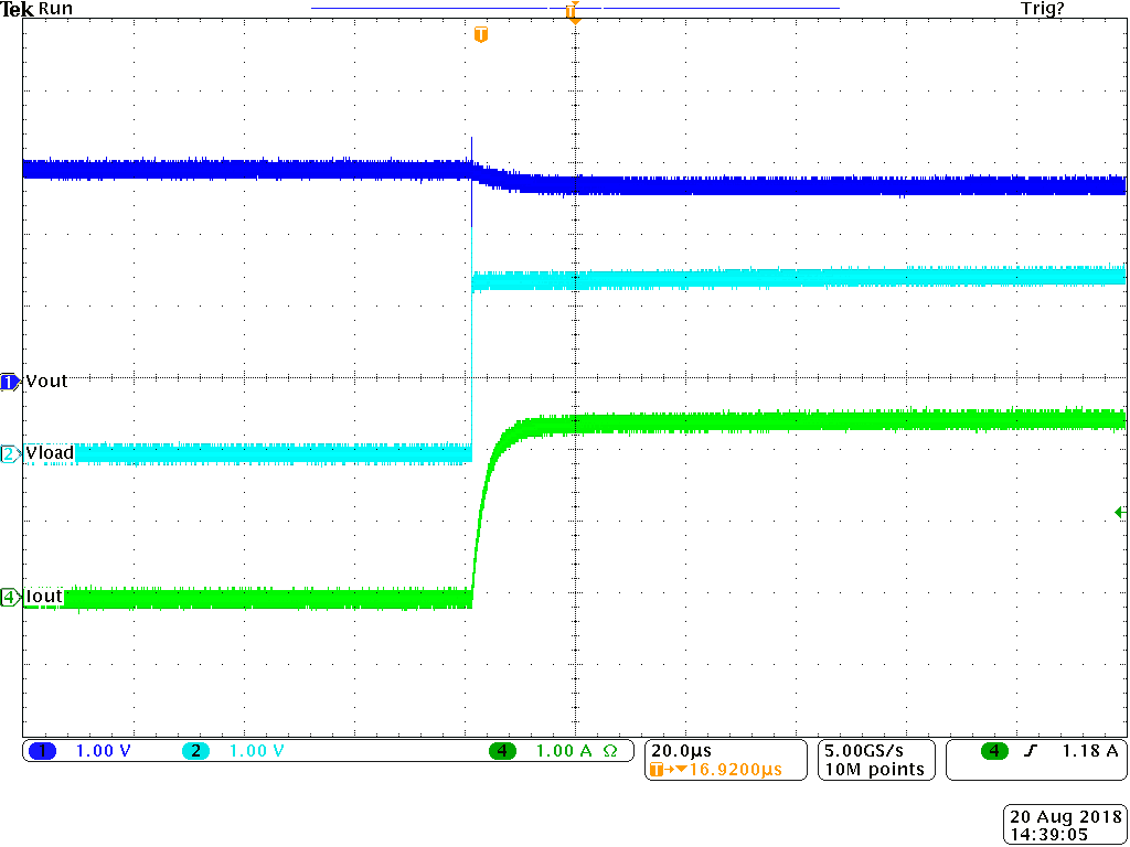
    I did a test, and below is waveform. Vin=3V and load is 1ohm. Part is enabled, then I apply the 1 ohm load on it. Dark blue is Vout, light blue is voltage on load, green is output current. 

    From my test, the current rise time is ~ 10us and voltage rise time is even faster.  Your clock is 10K and duty is 50%, so the turn on time for each cycle is 50us. Thus this time should be enough for current rise and voltage.

    I noticed that there's a small inductor(L7), what's this inductor used for? The voltage your measured is behind the inductor, correct? Is there any possibility that the inductor influence the voltage?

    Regards,

    Bob

  • Hi Bob,

    I short the inductor ,Iout seems no change. I noticed Iout rised as yours at the first time while dropped and acted as my picture upper.

    The circuit could just work under 1KHz .I'm confused about this.

  • Hi, Yang,

    We simulated it and the result shows no this problem at 10Khz. I will test on bench and send you result then.

    Regards,
    Bob
  • Hi, Yang,

    Sorry for late reply.

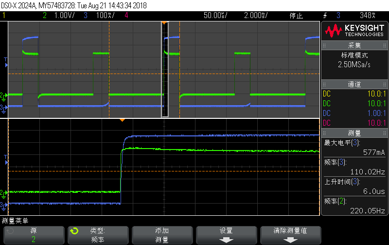
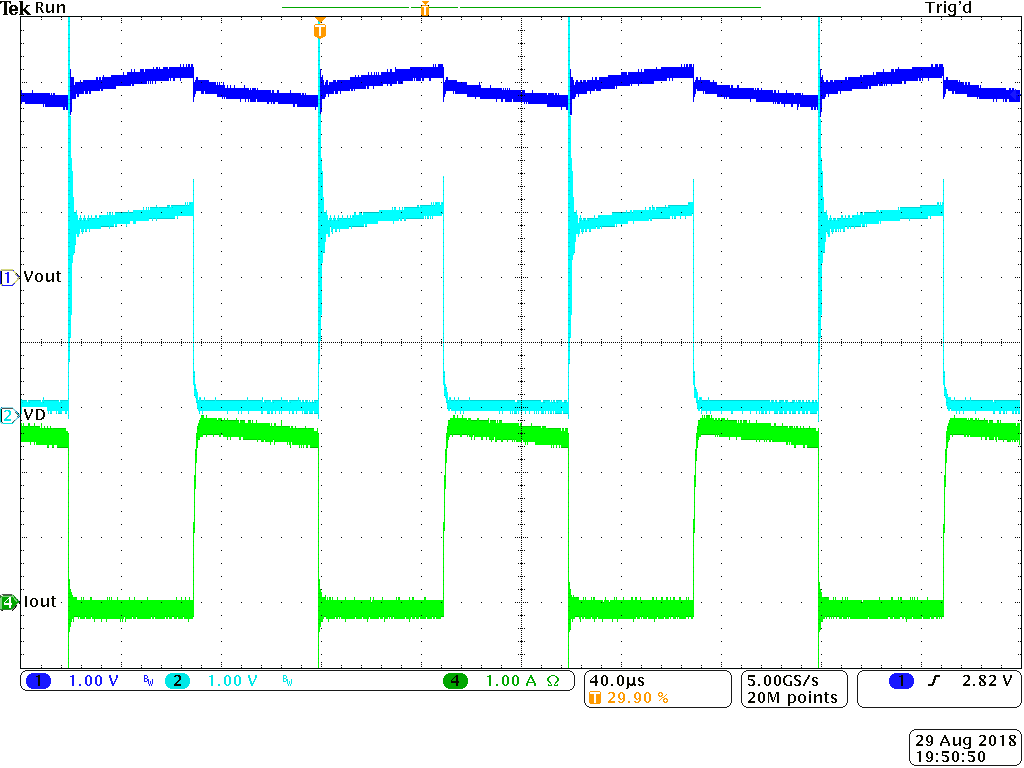
    Below is my bench test waveform, Vout is output of TPS2559, VD is drain of Mosfet(I used CSD16403), Iout is output current. My bench is TPS2559EVM+1ohm Power resistor + CSD16403. The TPS2559 setting is same as yours, Vin below is 5V, waveform is similar when Vin is 3V.

    Have you solved your problem? Is below waveform what your expect?

    Regards,

    Bob

  • Bob,

    Thanks for ypur support. It seems to be the MOSFET driver problem.