This thread has been locked.

If you have a related question, please click the "Ask a related question" button in the top right corner. The newly created question will be automatically linked to this question.

TUSB1310A: REFCLKSEL setting

Part Number: TUSB1310A
Other Parts Discussed in Thread: TUSB1310

Hello,

How are settle the REFCLKSEL1,0 signals?

In data sheet it seems to have two different ways:

Table 3-8. Strapping Options, the REFCLKSEL1,0 signals come from ULPI_DATA4,5 state value latching at reset release.

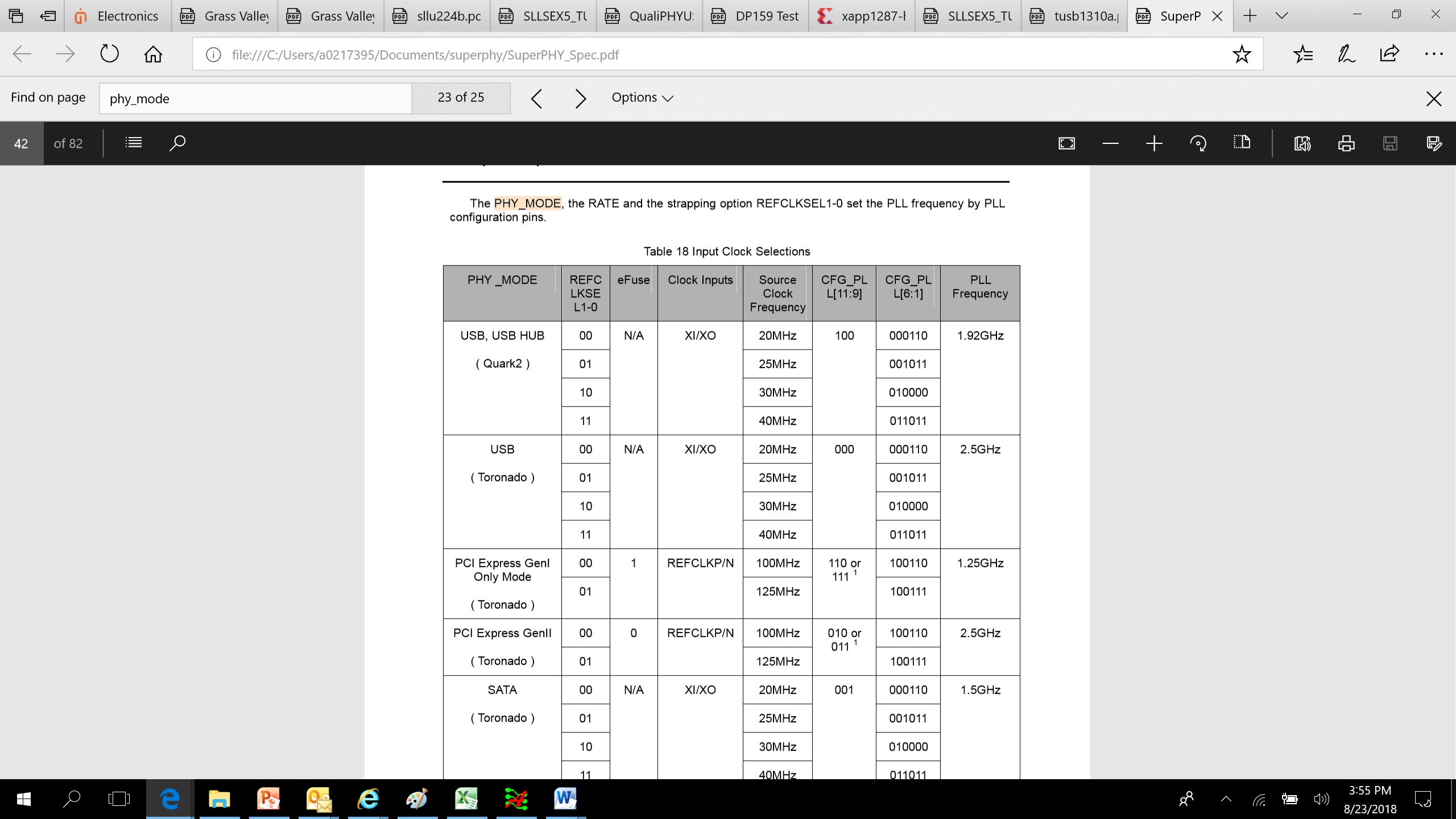
But page 22 it is written "REFCLKSEL1-0 is determined depending on the PHY_MODE pins"

So which one is the good?

Thanks,

Pierre.

  • Strapping Options seems more easy for application.
  • Thank Brian,

    But it doesn't fully answer my question.

    It seems there are two ways to set the REFCLKSEL1,0 signals, as explained in my first post.

    which has priority over the other?

    I mean if I want to use a non default mode, let's say REFCLKSEL1,0=b00, I can put a pull down on ULPI_DATA4 and 5.

    But as the PHY_MODE0 have an internal pull-up will that not have an effect on REFCLKSEL0?

    Thanks

  • you may confused, both REFCLKSEL  and PHY_mode  need to work together:, here is the table may help you understand.

  • Hello Brian,

    Thanks for your post, but this doesn't answer my question which was : how to set refclksel1,0 signals; by phy_mode1,0 or by ulpi_data5,4?

    By the way, I don't have this table in any of my tusb1310a documentation; from which document it comes from? can you provide it to me?

    Thanks,

    Pierre.

  • refclksel1,0 is from ulpi_data 4,5, but it's value is determined by phy_mode1,0. For example, in USB mode, refclksel 00 means 20Mhz, but in PCIE mode, refclksel 00 means 100MHz. they have to work together to get right REFCLK setting.
    this is TI PSS document, are you customer or TI FAE?
  • I'm a customer, and it would be nice if I can get this TI PSS document., it seems there are useful information into it.

    I think I'm starting to understand! but it's really badly explained in the documentation....

    So if I'm working in USB mode with a 40MHz external clock, so I have to do the following settings right?:

    phy_mode0 = 1

    phy_mode1 = 0

    ulpi_data[5,4] = b11

    Thanks,

    Pierre.

  • your setting is right. I will check if can give you the document
  • we can not send all document to customer, maybe some subset, does it OK?
  • I'm interested by all additional documentation compare to what I already have.

    For information, I have the following documents:

    _ tusb1310 data manual.pdf

    _ TUSB1310 Implementation Guide.pdf

    _ TUSB1310A Errata.pdf

    _ tusb1310a.pdf

    But as I do not know the content of your additional documentation I can't tell you what to send to me... please send me all what you can!

    Thanks,

    Pierre.

  • Hi Pierre,

    As I noted on another thread, the TUSB1310A device is an older USB 3.0 transceiver that is marked as not recommended for new designs. The device has documented errata and the USB specification has been updated numerous times since this device was released. While we can provide clarifications on the existing documentation of this device, we are not able to provide implementation support or internal design documentation.

    Regards,
    JMMN
  • ok, thanks, it is clear.

    My application is not for production, it is just a prototyping on FPGA, it's the reason why I have chosen this phy.

    But of course it must work!! you scare me when you write "the USB specification has been updated numerous times since this device was released"; I hope this phy can still work in front of a standard PC?

    Otherwise, do you have an other USB3.0 phy?