This thread has been locked.

If you have a related question, please click the "Ask a related question" button in the top right corner. The newly created question will be automatically linked to this question.

TL16C752D: About TL16C752D replacing TL16C752B

Part Number: TL16C752D
Other Parts Discussed in Thread: MAX3243

Hi dear supporting team,

my customer is using TL16C752D replacing TL16C752B, while in their p/l, they find the failure rate is around 100% (their R&D did not test it due to some mistake).  so it should be due to application issue. 

the issue is as below:


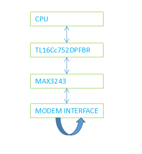
their block diagram is as below, TL16C752DPFBR  and CPU interface is parallel interface,TL16C752DPFBR and MAX3243 is using RS232 Transceivers interface(Programmable Auto-RTS and Auto-CTSModem Control Functions (CTS, RTS, DSR,DTR, RI, and CD)),MAX3243 output is MODEM interface.

       during the test, they use the external connection cable to loop back the MODEM INTERFACE transceiver signal,and sent by cpu through parallel interface to TL16C752DPFBR,then through TL16C752DPFBR receive the data back to CPU to judge whether the data sent and received are the same.

the phenomenon: CPU send one data, the received data is normal,  when CPU continuou sending 10 data, CPU receive the first data normal, the second data is 0, then after that no data received. if use B version, it is normal.  

pls help analyze what's the difference btw them cause the issue. tks a lot!


  • Hi Vera,

    Can you please share some more information about how the device is being used? If you could provide a schematic showing the UART connections and a list of register writes that are used to initialize the device it would be very helpful. Some things that would be good to know would be if the TX/RX FIFOs are being used and how flow control is being implemented. Also, will you please let us know the value stored in the LSR (register address 101) and IIR (address 010)?

    Regards,
    Max
  • hi  Max,

    thank you very much!TL SCH.docx

    the sch is and  the reg read out is as attached, and the baud rate is 9600. pls help review it and comment whether there is anything else needed. tks a lot!TL16C752 READ OUT.xlsx

  • Hello Vera,

    Are you able to probe the IOW, IOR, ChA, INT pins when you are sending data on an O-scope? I would like to see the timing of this.

    Can you also tell me what the clock frequency is going into the device?

    I would also like to see what the clock signal looks like during communication (Xtal1 and Xtal2 pins).

    In regard to your register read out file, something seems odd with the DLL and DLH registers. DLL and DLH should never change after you initialize them but from what you provided it looks like DLL and DLH seem to change after you send data.

    Lastly, what is FCR set to?

    Thanks,
    -Bobby
  • hi Bobby,

    thank you for the reply!

    for your questions, reply in your email. tks!

  • Hi Vera,

    Just closing off this thread in the forum since this discussion has been continued offline via email.

    Regards,
    Max