This thread has been locked.

If you have a related question, please click the "Ask a related question" button in the top right corner. The newly created question will be automatically linked to this question.

TUSB1002A: About Rx termination circuit

Guru 21045 points
Part Number: TUSB1002A
Other Parts Discussed in Thread: TUSB1002,

Hi team,


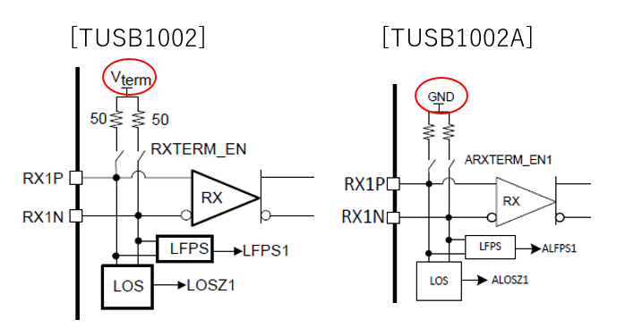
We understand that Rx termination circuit of TUSB1002 and TUSB1002A are different.

We would like to know the reason why this circuit was changed to.

Could you please let us know if you have any information?


Regards,

Kanemaru

  • Kanemaru

    The RX termination structure change from TUSB1002 to TUSB1002A is to provide better compatibility support with some USB3 devices on the market that do not comply to the USB common mode voltage requirement in the spec.

    Thanks
    David
  • Hi David-san,

    Thank you for the information.

    I understand. Thank you very much.

    Regards,

    Kanemaru

  • Hi David-san,


    I have additional question.


    I understand that some USB3 devices on the market can’t comply with the USB common mode voltage (1.65V(min), 1.85V(typ), 2.0V(max)).

    Therefore, you changed the Rx termination circuit and added option 330nF and R15 and R16.

    Is my understanding correct?


    [TUSB1002 and TUSB1002A Rx common mode voltage]


    [TUSB1002A datasheet]

    330 nF A/C coupling capacitors along with 220k resistors are placed on the RX2P and RX2N.

    Inclusion of these 330nF capacitors and 220k resistors is optional but highly recommended. If not implemented,

    then RX2P/N should be DC-coupled to the USB receptacle.


    Regards,

    Kanemaru

  • Hideto-san

    Your understanding is correct.

    Thanks
    David
  • Hi David-san,

    Thank you for always kind support.

    I understand. Thank you very much.

    Regards,

    Kanemaru

  • Hi David-san,


    I have one more question about TUSB1002 (Non A version).

    If some USB3 devices on the market can’t comply with the USB common mode voltage are connected to TUSB1002, could you please let us know behavior of device?


    [For example]

    -TUSB1002 can’t Link training

    -TUSB1002 can link training but can’t output a correct waveform etc.


    Regards,

    Kanemaru

  • Kanemaru-san

    Device will fail to be recognized as a USB3.0 device, it will recognized as a USB2.0 device.

    Thanks
    David
  • Hi David-san,

    I understand that TUSB1002 can't detect USB3.0 device and can detect USB2.0 so TUSB1002 output a irrelevant signal (don't stop signal ).

    Is my understanding correct?

    Regards,

    Kanemaru

  • Kanemaru-san

    It will depend on the behavior of the host when this issue happens. The old host will go into compliance mode while the new host, after time out of LFPS polling, will back to the beginning of USB detection state machine and start the whole process again.

    Thanks
    David

  • Hi David-san,

    Thank you for the detail information.

    I understand. Thank you very much.

    Regards,

    Kanemaru

  • Hi David-san,


    We understand that a behavior of HOST IC when this issue happens.

    We would like to know a behavior of sink device and TUSB1002.


    For example;

    -Sink device can’t response signal to HOST IC so can’t output SS signal (Because, HOST IC not succeed LFPS).

    -TUSB1002 can operate (not shutdown) but can’t output a suitable signal because SS signal are stopped.


    Regards,

    Kanemaru

  • Kanemaru-san

    I already addressed this in my previous response.

    It will depend on the behavior of the host when this issue happens. The old host will go into compliance mode while the new host, after time out of LFPS polling, will back to the beginning of USB detection state machine and start the whole process again.

    Thanks
    David
  • Hi David-san,


    I apologize for confusing you.

    I understand that your answer and would like to know a behavior of TUSB1002 when HOST IC can’t execute LFPS.

    I guess that a sink device can’t response (so HOST IC can’t detect a sink device.), then TUSB1002 can’t detect a sink device but TUS1002 is normal operation.

    Is my understanding correct?


    Regards,

    Kanemaru

  • Kanemaru-san

    Your understanding is correct, TUSB1002 is still in normal operation mode.

    Thanks
    David
  • Hi David-san,

    Thank you for always kind support and information.

    Regards,

    Kanemaru