This thread has been locked.

If you have a related question, please click the "Ask a related question" button in the top right corner. The newly created question will be automatically linked to this question.

SN65HVD230: CAN trasceiver

Part Number: SN65HVD230

Hi

I design a custom board and for CAN transceiver i used SN65HVD230. I tested can controller in loopback mode. it's working correctly. But when i measure transceiver voltage Vl = Vh = 1.5v  . I know that when bus is idle Vl , Vh have to be 2.3v. please help me to find what is wrong.

  • Hi Sadegh,

    The recessive state is only weakly biased to 2.3 V (via ~35 kOhms), and so it can be sensitive to leakage currents. Is there anything on the CAN lines that may present some loading? What is the input impedance of your voltmeter (or oscilloscope prove, etc.) you are using to measure the voltage?

    Regards,
    Max
  • Thanks for your quick answer
    There is nothing on the CAN bus, but two LEDs are connected to can controller. I check other devices with my voltmeter and there wasn't any problem.
    In the CAN bus, there is only one node. Can be this problematic?
  • Sadegh,

    Sorry it took a little while to get back to you; Monday was a holiday here in the US.

    Having one node can be problematic for communication since the transmitting controller expects to receive an acknowledgement from the receiving nodes to confirm successful reception of each frame. It should not affect the recessive signal level, though. Just to confirm - you have no resistances, no capacitances, no protection diodes, and no other transceivers (even powered-down ones) connected to the CAN bus when you take this measurement, correct? Would it be possible to take a resistance measurement from CANH to ground and CANL to ground with the board unpowered to see if there is some leakage in the PCB?

    Also, are you getting the same voltage at both CANH and CANL? And, is the TXD signal always pulled high for the measurement, or is it toggling/floating?

    Lastly, could you please let me know the model number for the voltmeter?

    Regards,
    Max
  • Thanks for your answer. I hope you have spended nice holidays.

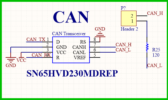
    this is the schematic.

    I measured resistance and voltage between the transceiver lines and ground. They are as follows :

    Resistance beween CAN_ Tx  and ground  =  43K

    Resistance beween CAN_Rx  and ground  =  5M

    Resistance beween CAN_H  and ground  =  14K

    Resistance beween CAN_L  and ground  =  14K

    Voltage beween CAN_ Tx   and ground  =  3.2V (always pulled high)

    Voltage beween CAN_ Rx  and ground  =  2.2V

    Voltage beween CAN_ H   and ground  =  1.5V

    Voltage beween CAN_ L   and ground  =  1.5V

    Model number of my voltmeter is  : VICTOR VC97

  • I forgot to say I tested my CAN controller and I understood that my CAN controller only can receive the message and can't send any message.
  • Sadegh,

    Thanks for providing this information, it is very useful. The 14-kOhm resistance measured from CANH and CANL to ground is lower than I would have expected, since the input resistance of these pins should range from 20 kOhm to 50 kOhm (and typically be about 35 kOhm). Was Header 2 shorted or open for this test? Have you tried measuring the same resistances with the HVD230 uninstalled? I'm asking about this since leakage resistance to ground is the most common cause of lower recessive levels.

    Also, just to mention - CAN communication is not all that sensitive to differences in recessive level voltages since the physical layer is based on differential signaling (and is specified across a relatively wide operating common-mode range). So, the lower recessive level alone should not be a problem. I still think it makes sense to make sure we understand why you are seeing this, but I wanted to mention that in case resolving this was gating any other testing you had planned for this design.

    Max
  • Max,
    Thanks for your help
    when header2 is open value of resistance is 25k. I haven't tried to measure the same resistances with the HVD230 uninstalled. I tested
    the CAN controller . I can only receive message and i can't send any message. when i receive a message i can't acknowledge it. i can't send any message. I set the CAN controller to normal mode. 2.2 volt on CAN Rx is not unusual? 43k resistance between CAN Tx and ground is not unusual?
    I can't understand english well. i dont understand this sentence( I still think it makes sense....).

  • That's a good point, 2.2 V is lower than I would expect to see on RXD. Can you verify that the VCC voltage is close to 3.3 V? (The high-level RXD output will track VCC, and the recessive levels will be lower with lower VCC as well.)

    What happens when you try to transmit a message (or an acknowledge bit)? Does the TXD line from the controller to the transceiver toggle at all? If so, do you see toggling on the CANH/CANL lines that corresponds to TXD?

    The TXD resistance is also a little lower than I would expect from this device. I'm not sure what might cause that at the moment other than other resistances or leakage paths on the PCB. (Again, this could be confirmed via measurement with the transceiver device removed.) Also, forgive the basic question, but since multiple voltages/resistances seem off can you also please verify the correct orientation of the device on the PCB?

    By the way, do you have multiple systems that are all showing the same behavior, or are you working with a single prototype at the moment?

    Regards,
    Max
  • Sorry, it took a  while to get back to you.

    The problem resolved. I replace the transceiver with another one and now the CAN controller works well. I have a question. the old transceiver part number is "VP230 41M AIDG4"  and the new transceiver part number is "VP230 32M APKT". what is the difference between them? 

  • Hi Sadegh,

    These are same parts. The middle line on the top-side marking indicates the date and location of assembly. The first digit is the least-significant digit of the year, the second digit represents the month, and the third digit represents the site. Therefore, the "41M" units would be from January 2014, the "32M" units would be from February 2013, and both were assembled in Mexico. The final line of the top-side marking is just a lot trace code so that we can track down the units to an individual wafer lot.

    I'm glad to hear the issue was resolved. In case the initial unit needed to be replaced because it was observed to be damaged/defective, you may want to double-check the storage conditions that these devices endured. I just wanted to mention that since these are older date codes.

    Let me know if I can help with anything else.

    Regards,
    Max