This thread has been locked.

If you have a related question, please click the "Ask a related question" button in the top right corner. The newly created question will be automatically linked to this question.

SN65LVCP402: VML sinaling Interface

Guru 19785 points

Part Number: SN65LVCP402

Hi Team,

Could you please tell me about the following questions.

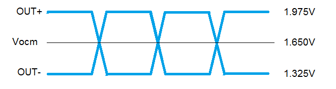
1). What is VML singaling interface ? Could you please share us the output schematic ?

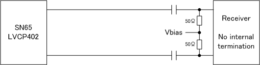
2). If we have SN65LVCP402 output to FPGA, how should we terminate the high speed differential line at the FPGA input pins ? Should we connect 100 ohm between the +/- line ?

3) Do you recommend to AC couple the high speed line ?

Best Regards,

Kawai

  • Hi Team,

    There is no application schematic or interface example shown in the datasheet.
    Please help us how we can interface correctly to other devices.

    Since our customer is having trouble using this device, your quick response would be greatly appreciated.

    Best Regards,
    Kawai
  • Hi,

    I have attached the output voltage levels given by the datasheet specifications. 

    The expected termination is 100 Ohms differential at the connected receiver input. Many FPGAs already incorporate the 100 Ohm receiver termination.

    In most cases the receiver will not be compatible with the Vocm  and AC coupling will be needed.

    Regards,

    Lee

  • Hi Lee-san,

    Thanks for the information.

    When AC coupling the output, I am understanding that 100 ohm differential termination is only required at the receiver input only.

    4). If AC coupled, where would you recommend to place the AC coupling cap ? Is it close to the receiver side ?

    5). Is the following general connection correct for this VML ?

    Best Regards,

    Kawai

  • Hi Kawai-san,

    Yes since there is no termination internally an external termination should be placed as close as possible to the Rx device.  Some receivers develop there own internal bias.  If this Rx does not, then you are correct to establish a Vbias common mode voltage to optimal Rx performance.

    4. I would recommend to place the AC coupling closer to the Rx side of the interface, but the actual location is not critical.  I would avoid placing the AC coupling within 10-25mm of the LVCP402 output to minimize any reflections.

    5. Yes this connection is correct.

    Best Regards,

    Lee

  • Hi Lee-san,

    Thank you so much for your support !!

    Best Regards,

    Kawai