This thread has been locked.

If you have a related question, please click the "Ask a related question" button in the top right corner. The newly created question will be automatically linked to this question.

SN65LVCP408: signal at output port 7 twisted when changing SWT

Part Number: SN65LVCP408

We currently found a issue of SN65LVCP408 in our video matrix application.

We are feeding 7 sets of differential clock signal as the input signal of the SN65LVCP408.

The typical application is to pair the input and output by switching the different profiles. When switching the profile, we will change the status of PIN "SWT"
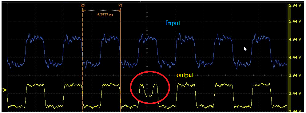
We found the output signal at port 7(only port 7) twists whenever we switch the profile from profile A and profile B.

Input port 7 is directed to output port 7 in both profile A and profile B.

In our application, if the output clock signal twists at port 7, output video will flash and come back. That's not something we want. We want a seamless switch.

We are not sure anything we miss in our circuit....

If possible, can anyone provide the reference design of this SN65LVCP408? There are not much info. on the website.

Attachments are our circuit and measure signal

  • some one will look at this issue soon
  • do you have this issue if you don't switch profile? we can't find reference design too.
  • Hi Andy,

    Do you have the register programming?  I would like to go through the port configurations.

    Do you have a scope wavefrom of the SWT transition and the odd clock waveform?

    What are the other 6 input clock frequencies?

    Regards,

    Lee

  • No, it only happens when switching.
  • Hi, Lee,

    I'll get you the register and the SWT transition later. The other clock frequencies are 148MHz.
  • Hi, Lee,

    The register is here. We set the profile A and profile B identically on purpose.

    register address        value               profile A

    0000 0000                 0000 0000        output 0 -> input 0          

    0000 0001                 0010 0000        output 1 -> input 1

    0000 0010                 0100 0000        .

    0000 0011                 0110 0000        .

    0000 0100                 1000 0000        .

    0000 0101                 1010 0000

    0000 0110                 1100 0000

    0000 0111                 1110 0000       output 7 -> input 7

                                                         profile B

    0000 1000                 0000 0000      output 0 -> input 0    

    0000 1001                 0001 0000      output 1 -> input 1

    0000 1010                 0010 0000

    0000 1011                 0011 0000

    0000 1100                 0100 0000

    0000 1101                 0101 0000

    0000 1110                 0110 0000

    0000 1111                 0111 0000      output 7 -> input 7

    0001 0000                 1000 0000     swap via SWT pin

    The clock starts twisting after  "SWT" rises above VIH  6 ns.

    We also notice the clock only twists on SWT rising edge, but not falling edge.

  • The issue also happened when we did't feeding any signal on the other six ports.
  • Hi Andy,

    Thanks for the additional information. I do not see anything wrong with the register setup you provided.

    Just checking:

    Have you verified the register contents?

    Does this happen with multiple SN65LVCP408 devices?

    Thanks and Regards,
    Lee
  • Hi, Lee,

    What do yo mean "verify the register contents"? Is there any specific register we need to check?

    Yes, it happens with multiple devices.

    There are two things we want to ask:
    1. Why does clock signal twist at port 7 when SWT rise? Is this a potential issue from IC?

    2. We found another way to switch profile without the need of SWT.
    We simply modified the port 0~port6's register in profile A (, port 7 does't get modified ) through I2C when we want to switch. We didn't really switch from profile A to B. It still stayed in profile A, but it looked like we did because the content was changed.
    By doing this, we didn't rise SWT and twist our clock signal. But we are not sure this is a valid way to do so...or is there any side effect ?
  • I just wanted to know if you could read back all the registers and get the expected results.

    1. It may be part of the way the device operates.  I am working to put together hardware to test this function in the lab.

    2. This sounds like another method to accomplish the same type of function.

    Regards,

    Lee

  • OK, I see.
    Please let me know your hardware test result later.
    Thank you.