This thread has been locked.

If you have a related question, please click the "Ask a related question" button in the top right corner. The newly created question will be automatically linked to this question.

DP83822I: Scheamtic and 100BASETX and 100BASEFX Switch

Part Number: DP83822I

Hi

We plan to use this to switch between RJ45 and Fiber using a PB switch.

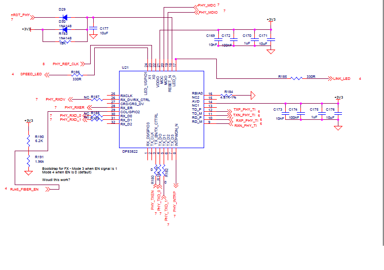
Is there a sample schematics for this part?

How does the TD_M,TD_P, RD_M, RD_P connect to both RJ45/Mag and SFP/Fiber? What happens if both Rj45 and Fiber link present?

Thanks.

  • Hi Barani,

    The DP83822I cannot have both a copper and fiber link present at the same time.

    For a schematic, I would suggest looking at the EVM which has both copper and fiber options that are selected by component population. You could perhaps place some switching device/MUX between the PHY and the copper/fiber connections.

    www.ti.com/.../snlu179.pdf

    Best Regards,
  • Thanks Rob for the info. We found a mix to switch. Once I have the schematic I will send you for review.

    On auto selecting FX mode - COL pin 29 is set to 1 for FX and 0 for TX mode. Pls confirm.
  • Hi Barani,

    For the PHY to alternate between FX and TX using COL pin, the strap must change from mode 1 to mode 2, or mode 3 to mode 4.

    The modes are entered using a DC voltage defined as a ratio of VDDIO level.  See table 10 in the datasheet.

    If you plan to change often between FX and TX, I would suggest using register configurations.

    Best Regards,

  • Thanks for the info. We don't expect this change is often. Just an option.  Attached a schematic and let me know any feedback. It looks to me that 

    - we may need a mux on COL strap res value for mode 3 and mode 4

    - once the user changes to fx mode - enable mode 3 and do PHY reset so it can use strap value to change mode 3. Do the same when user changes to TX mode.

  • Hi Barani,

    Your schematic looks ok. I need to add that you should have a parallel pull-up resistor of 2.2k - 2.49k with your LED_1 and LED_0 current limiting resistors.

    I think your RJ45_FIBER_EN signal and scheme will work if you can drive a high on that pin. When you need FX mode 3, you should hi-z whatever may be driving the RJ45_FIBER_EN signal.

    Your sequence for changing modes is also correct.

    You would set the state of RJ45_FIBER_EN as you want(hi-z = FX, 0 = TX) then send a RESET pulse to the PHY.

    Best Regards,