Part Number: AM26C31
Other Parts Discussed in Thread: AM26LV31E
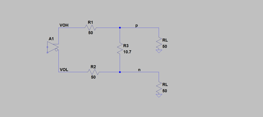
Customer is trying to use AM26C31 to drive a differential input that can handle only 600mv pkpk diff. Since the output swing of this device is too high he is using a series resistor at each leg and another resistor in parallel with the load. He did a simple voltage divider calculation to determine the value of the shunt resistor (R3 in the drawing shown below) but when he looked at Figure 3 of the data sheet he got confused about the common mode voltage of the output.
Because from VOH and VOL the nominal VOCM = (VOH+VOL)/2 but on Figure 3 it seems to indicate that there is a 1.3V offset. So he is not sure if the resistor value he calculated is correct.
His questions are
1- what is the common mode nominal value>
2- If he needs a 600mV diff signal at the input of my device or that the load is the value of R3, shown attached, correct?
3- Do you have a spice model for this device?
Thanks.