A related question is a question created from another question. When the related question is created, it will be automatically linked to the original question.
If you have a related question, please click the "Ask a related question" button in the top right corner. The newly created question will be automatically linked to this question.
XIO2001: IBIS model - EIO1G4A1W0_TX, pullup and pulldown information
Sorry for the late reply. After speaking with the modeling team it seems that when there is NA column in pulldown or pullup table, it implies weak and strong corners characteristic is not modeled. Only typical corner data is present. The fields you mentioned in your last post represent the corners of the simulation and will be called by the simulation software when specified.
Thanks for your support. I have additional questions.
Q1). Regarding your information, does that mean you cannot simulate the IO characterisitc correctly with this model ?
Q2) Isn't this model only prepared for low speed signal IOs ?
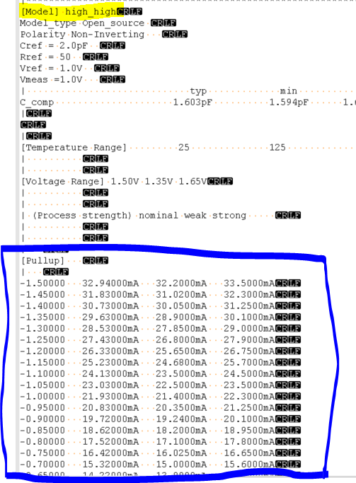
Q3). I believe below infomation are "Voltage", "I(typ)", "I(min)", "I(max)". If correct, there is no current (Ityp=0.0). Can you say this is "Typical" Characterisitic ?
You should be able to simulate with this model. The Pulldown and Pullup sections refer to different pins in the IBIS model, in other words this model is not meant to use the Pulldown and Pullup pins in your simulation software.
Your earlier understanding is correct. The actual I/O characteristics are called in the "Driver Schedule" portion of the model. Are you running into issue using some software?
Can I understand that [ Model EIO1G4A1W0_TX] does not uses the pullup/pulldown information in it's model, however, it will call pullup/pulldown information which is listed in the "high_high", "low_low", "mideum_high", or "medium_low" model ?
This is customer question how it is modeled and I also wanted to deepen my understanding.
[Driver Schedule] is used to describe a driver with pre-emphasis/de-emphasis behavior. High_high, medium_high and etc describe timing differences between different voltage levels that constitute pre-emphasis behavior. You can find more detail regarding this driver schedule in IBIS specification document attached. the Pullup (for rising edges) and pulldown (for falling edges) information in the blue box is information that is actually called when simulating this driver.
Is there any more support needed for this issue? If so please reply with any relevant details so that I can further assist you. For now I will be marking this thread as "TI Thinks Resolved".