This thread has been locked.

If you have a related question, please click the "Ask a related question" button in the top right corner. The newly created question will be automatically linked to this question.

AM26C31: AM26C31 Figure.9 in the datasheet

Part Number: AM26C31

Hello team,

I would like to confirm what shows Figure 9. Differential 120-Ω Terminated Output Waveforms (Cat 5E Cable) in AM26C31 datasheet.  I can not understand Y(black) A/B(red) because  AM26C31 is singe-end to differential converter and Driver.


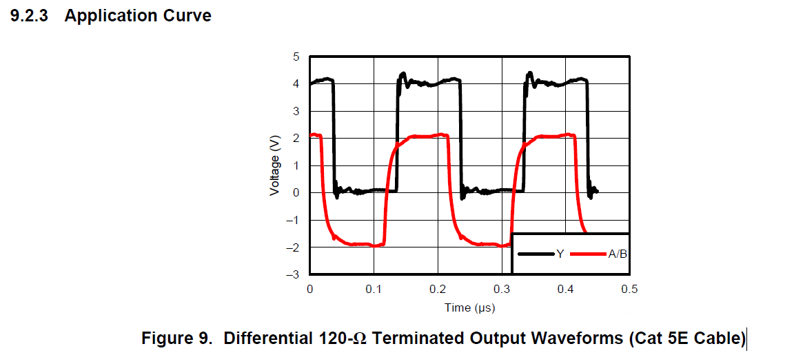
Do A/B mean differential signal? However when I consider the propergation delay, I do not meke sense.

Woudl you please advise me?

Best Regards,
Akihisa Tamazaki

  • Hello Tamazaki-san,

    Yes, the red signal on this plot is the differential voltage between the A and B signal lines. It can be hard to tell propagation delays for signals that are periodic. In this case, although it looks like the differential output precedes the input, but there is actually a long propagation delay from the input signal to the output signal. This is because the output signal is measured at the end of a cable. (A typical estimate for propagation delays of these cables is ~5 ns for each meter.)

    Please let me know if this is unclear or if you have any further questions.

    Regards,
    Max
  • Max-san,

    Thank you for your reply. I understand it.

    Best Regards,
    Akihisa Tamazaki