This thread has been locked.

If you have a related question, please click the "Ask a related question" button in the top right corner. The newly created question will be automatically linked to this question.

DS125BR401A: DS125BR401ANJYR placement and location recommend for SATA interface

Part Number: DS125BR401A
Other Parts Discussed in Thread: DS125BR401

Hello Sir,

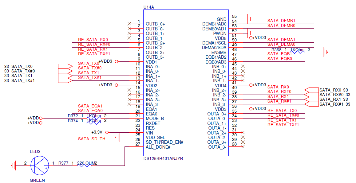
We're using the DS125BR401A re-driver for SATA interface as picture below.

We'd like to confirm the placement location.

Case1.

PCH -> DS125BR401A trace length 2.2"

DS125BR401A -> Connector trace length 9.6"

Case2.

PCH -> DS125BR401A trace length 10"

DS125BR401A -> Connector trace length 2.4"

Could you please help to provide placement suggestion to us?

Thank you.

  • I would recommend to use the DS125BR401A farther away from the PCH (10" option).

    I would also recommend to give an option to program the DS125BR401A with the SMBus.  This allows for more control over the signal conditioning functions.

    Regards,

    Lee

  • Hi Carlos,

    My colleague - Lee - may have additional comment but here is some recommendation:

    Case 1: DS125BR401A has linear receivers on INA side. Therefor link training would go through DS125BR401 INA to OUTA. INA should be used when there is a short trace to the transmitter.
    PCH -> 2.2" Trace length -> DS125BR401A (INA_0 through INA_3) -> DS125BR401A(OUTA_0 through OUTA_3) driving 9.6" trace length

    Case 2: DS125BR401 INB limiting side is more tuned for longer trace length. Therefor in this case, we can do the followings:
    PCH -> 10" Trace length -> DS125BR401A(INB_0 through INB_3) -> DS125BR401A(OUTB_0 through OUTB_3) driving 2.4" trace length

    Also, the recommendation is to start off with low equalization and no de-emphases - allowing heavy lifting equalization to be done by the receiving side. You can increase amount of equalization if needed.

    Regards,,nasser