This thread has been locked.

If you have a related question, please click the "Ask a related question" button in the top right corner. The newly created question will be automatically linked to this question.

HD3SS3212: HD3SS3212 issue

Part Number: HD3SS3212

HI

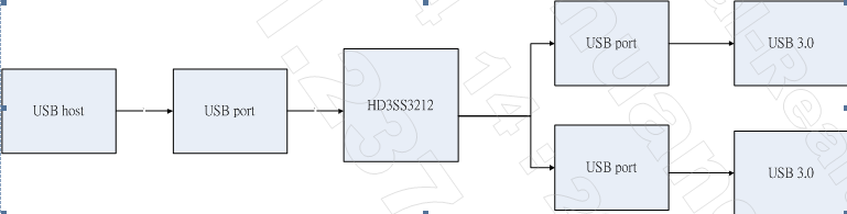
I use the HD3SS3212 to build a USB 3.0 (Gen2 ) switch board for some project, I have some issue.

The applcation is below , like a wire ,that  USB host can chose link USB port 1 or port 2.

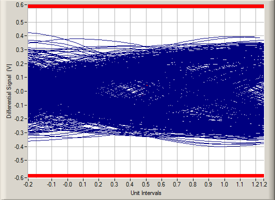
  1.  The Impedance trace is 90+- 5%,but eye is very bad, the trace length is 2600 ~ 2800 mils,the layout rule seems fine
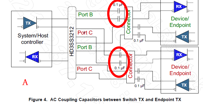
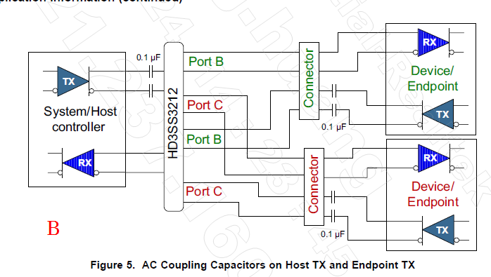
  2. is AC coupling is need? My applcation need to reference A or B?
  • Both A and B are shown assuming HD3SS3212 is designed on the same PCB as the System/Host controller plus the connector. How does your design look like? Do you have connectors on both side of HD3SS3212 PCB design?

    Thanks
    David
  • like this , usb type B port on the top , and two type A port below the pcb ,between type A and B have a  HD3SS3212.

  • Since connectors are used on both side of HD3SS3212, the host and device termination and AC coupling scheme is not known. I would do the following to make sure the USB are properly AC coupled and terminated.

    But eye closure could also due to too large a channel loss at 10G, have you tried a shorter cable?

    Thanks

    David

  • Hi David

    It's weird that ac cap's value is different from the spec,it's not 0.1uF?

    Also what's the R1~R4 do? It's needed?

    So the whole design like this?(My usb host is pc usb 3.0 host, the device just a normal usb 3.0 device ,like any 3.0 usb disk)

    I can try to reduce the cable , is there have any layout length rule?

    thanks you

  • The diagram is correct.

    I actually made a mistake in my diagram, the 220k pulldown needs to be placed between the AC coupling caps and HD3SS3212. Since the RX lanes are AC coupled, 220k is needed to properly biased the HD3SS3212.

    Since connector is used on both side of HD3SS3212 and different host/device can be plugged, you can't assume all host/device are USB compliant and have internal AC caps. Putting AC caps on both TX and RX is a attempt to address non-compliant USB host/device. Since HD3SS3212 is a mux, the total possible capacitance is:

    Total capacitance = 1/(1/Host AC caps + 1/HD3SS3212 TX caps + 1/HD3SS3212 RX caps + 1/Device AC caps). The RX caps is min 297nF min and 363nF max. Total capacitance is 75nF min and 265nF max. Calculation has to be made for all possible combination cases to meet the total capacitance requirement.

    USB3 max cable length is 3m. But if connectors are used on both side of HD3SS3212, then you could have a worst case of 3m on both sides, results in 6m total cable length + loss from HD3SS3212 board, which will not work as it is a violation of the USB spec.

    A better solution is to use USB plug on one side and USB connector on the other side, and instead using HD3SS3212, using TUSB1042 since TUSB1042 has a RX equalizer that can help compensating the cable loss, effectively extending the 3m cable length.

    Thanks
    David