This thread has been locked.

If you have a related question, please click the "Ask a related question" button in the top right corner. The newly created question will be automatically linked to this question.

TLK10232: Clock output is not coming from TLK10232CTR

Part Number: TLK10232

I use 1gbit/s sfp module  and configure it to send traffic  but could not receive output clock (156.25 MHz) from channel A

device_addr 0x1e, addr 0xf
0x1403

device_addr 0x1e, addr 0x10
0x0

 device_addr 0x1e, addr 0xd
0x2f80   possible problem with divider , i tried to set 8 16

device_addr 0x1e, addr 0x2
0x831c


Could you help me how to test it ?

  • Taras,

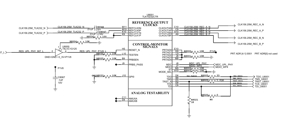
    this kind of issue could be very hard to debug, could you provide a simple block diagram of your system so that I have a better idea of whats going on? Is the TESTEN pin pulled high? We recommend that this pin be pulled low and having this pin high can cause issues with not seeing clock on CLOCKOUT pin. Device_addr 0x1e, addr 0xd 0x2f80 is the correct value for default operation of the CLOCKOUT pin. What are the values device_addr 0x1e, addr 0x3 and 0x4?

  • Hi, thanks for quick replay

    and values:


    reading phy 2, device_addr 0x1e, addr 0x3
    0x78c8
    reading phy 2, device_addr 0x1e, addr 0x4
    0xd500

    clock out are inputs for si-5345 (silicon labs)
    and I read status of si-5345
    some progress with divider if set it to "1"     device_addr 0x1e, addr 0xd  0x2f00

    I get signal on input of si-5345 , but error "out of frequency" still stays on

    One more problem: we noticed  that we couldn't get link 2 up with same SFP module and connection scheme, only link1 is UP

  • Taras Shevchenko said:
    One more problem: we noticed  that we couldn't get link 2 up with same SFP module and connection scheme, only link1 is UP

    we figure out , it is not TLK10232 problem

    but clock still missed

  • Taras,

    What have you selected as the OOF reference? Also could you provide the Channel A and B register settings?

  • We use external crystal 50MHZ for si5345 clock  and    156,25 MHZ as reference clock for TLK10232   
    if I quite understand about register settings
     - channel A  0x1e 0x1 0xb24
    - channel B  0x1e 0x1 0xb24
    or please specify which register do you need
    Just remind we use 1gbit/s SFP

     SERDES PLL Multiplier are 16,5  should it set to 16 ?

  • Taras,

    This correct HS PLL Multipler should be 16 and LS PLL Multiplier should be 8.

    The registers below are the registers that I would like to the value for your current configuration. Also when testing are you providing input data to the device?

    REFCLK_FREQ_SEL_1
    REFCLK_FREQ_SEL_0
    CLKOUT_SEL[3:0]
    CLKOUT_DIV[3:0]
    CLKOUT_ EN
    CLKOUT_POWERDOWN
    HS_ENPLL
    LS_ENPLL
    HS_PLL_LOCK
    LS_RX_RATE [1:0]
    LS_MPY[3:0]
    LS_PLL_LOCK
  • dev 0x1e reg 0x1d  value  0x0
    REFCLK_FREQ_SEL_1    = 0
    REFCLK_FREQ_SEL_0   = 0

    dev  0x1e reg 0xd  value 0x2f80
    CLKOUT_SEL       00x0 = Selects Ch A HS recovered byte clock as output clock

    CLKOUT_DIV       1000 = Divide by 4 (Default 4'b1000)

    CLKOUT_ EN        = 1      Allows CLKOUTx_P/N output to toggle normally

                        CLKOUT_POWERDOWN  0 = Normal operation (Default 1’b0)

    dev 0x1e reg 0x2 value 0x831b
    HS_ENPLL = 1 Enables PLL in HS serdes (Default 1’b1)

     dev 0x1e reg 0x6 value 0xf114

    LS_ENPLL 1 = Enables PLL in LS serdes (Default 1’b1)

    LS_MPY = 0100     8x

     dev 0x1e reg 0xf value 0x1403

    HS_PLL_LOCK = 1

    LS_PLL_LOCK= 1

     dev 0x1e reg 0x7 value 0x0

    LS_RX_RATE =0      00 = Full rate (Default 2’b00)

    Malik Barton57 said:
    Also when testing are you providing input data to the device?

    Yes we send 100 packets  after that we get

              HS_PLL_LOCK = 1

    LS_PLL_LOCK= 1

  • Taras,

    These settings look correct. Could you tell me again the mode you intend to use with this device? Are you seeing nothing on the CLOCKOUT pins outputs or is their a clock at the wrong frequency? Could you give me more info on how you are testing the device, such as simple 1, 2,3 steps?
  • Hi Malik, that's what we do:

    1) Configure TLK10232 as mentioned before
    2) Read alarms of si5345
    it's = loss of clock signal (LOS)  and out of frequency (OOF) error at specified input

    after that we try to set different TLK10232 dividers by this register

     Device Address: 0x1E   Register Address:0x000D  Default: 0x2F80

    and read status of si5345

    if we set it to 0x2f00

     (LOS) at specified input disappeared , but OOF error is still stays on

  • Taras,

    Sorry for the late reply. I believe that a data path reset may be needed before the reading the alarms of the si5345. This can be done by writing Device Address: 0x1E Register Address: 0x000E bit 3 to 1. This may help your issue by resetting the data path after configuration. Could you provide a scope capture of the TLK10232 CLKOUT pins and ensure a clean output? Also please be sure that these outputs are AC coupled.

  • Taras,

    Is there any more support needed for this issue? If so please reply with any relevant details so that I can further assist you. For now I will be marking this thread as "TI Thinks Resolved". If you have resolved your issue, please post the solution to the original problem/post for others with similar issues.