This thread has been locked.

If you have a related question, please click the "Ask a related question" button in the top right corner. The newly created question will be automatically linked to this question.

DP83867IR: RGMII 10/100Mbps mode transmission failed

Part Number: DP83867IR

Hello.

I'm trying RGMII mode 100Mbps with the PHY and our MAC.

In case of RGMII mode, I could not see the transmission succeeded whereas the reception was successful.

In my test, the  data signals are output from the MAC to the PHY. And then, the PHY output coded signals to my PC. And the PC captures it.

Because I could confirm the transmission in MII 100Mbps mode, HW from the PHY to my PC should be OK.

I attached image files of the signals from the MAC by an oscilloscope at the bottom. If internal delay added, it looks no problem.

A clock for transmission data  is output from the MAC and goes to "GTX_CLK" (not TX_CLK) of the PHY.

Register settings for the PHY are shown in below. I confirmed these register were set as expected with reading back the values.

Address : Value

0x0000: 0x2100   /** 100M, Full Duplex and Auto Negotiation OFF */

0x0010: 0x5028  /** Disable auto neg for MDI/MDI-X **/

0x0032: 0x00D3  /** Enter Tx and RX Clock delay in RGMII configuration register */

0x0086: 0x00FF  /** Internal Delay Configuration : 4ns */

I appreciate it if you give me any suggestion.

Is there any lack in my settings?

Best regards,

Tsunokawa

  • Hi user,

    It can be common for the RGMII delay to be set on both the MAC and the PHY side, which then cancel each other out. It seems from the scope shot, that the 4ns delay is already implemented coming out of the MAC. Please eliminate the delay on the DP83867 side or the MAC side and retest.

    As you mentioned, receiving data already indicates your PHY is OK.

    Best Regards,
  • Hello Rob,

    Thank you very much for the suggestion.

    I tried eliminating the TX delay, however, I still could not see the transmission succeeded.(I had misunderstood that the data was captured with rising edge of the GTX_CLK, so I added the delay. Now I realized the data wold be captured with falling edge of the clock.) Since I'm trying 100Mbps communication, the clock frequency is 25MHz (40ns). So I think the delay have not had so much effect, but it is better not to add the delay.

    Now the register setting I tried is below.

    0x0000: 0x2100   /** 100M, Full Duplex and Auto Negotiation OFF */

    0x0010: 0x5028  /** Disable auto neg for MDI/MDI-X **/

    0x0032: 0x00D1  /** Only RX Clock delay in RGMII configuration register */

    0x0086: 0x000F  /**only RX Internal Delay Configuration : 4ns */

    Is there anything more I could try?

    Best regards,

    Tsunokawa

  • Hi Tsunokawa,

    Eliminating the delay on 867 should have worked. for you if you have a 4ns delay from your MAC already.

    Can you tell me what you mean by the transmission does not succeed? What does your test bench look like?

    Best Regards,
  • Hi Rob,

    Thank you for the response.

    Using "Wire Shark", I'm monitoring the ether frame from the PHY. So "transmission does not succeed" means that I could not see ether frames with the Wire Shark.

    Sorry, I have not seen the output of the PHY directly with oscilloscope. However, In case of MII mode, I could see the frames from the PHY with the Wire Shark. Therefore, I assumed HW from the PHY output to my PC had no issue.

    Best regards,
    Tsunokawa
  • Hi Tsunokawa,

    So to confirm, you have a problem in RGMII mode. In MII mode, the PHY is operating normally?

    In your script are you restarting your PHY between changing between MII and RGMII? Do a software restart when changing interfaces by writing register 0x1f = 0x4000.

    I would ensure your configuration on the MAC is correct for RGMII mode. It seems like your MAC is aware a link is present and the RGMII mode is active. 100M link speed means GTX_CLK = 25MHz.

    Transmission doesn't succeed but you are seeing the signaling to the PHY working. I'd expect that your PHY isn't going into RGMII mode as you are expecting. So ensure the restart of the PHY is occurring.

    Best Regards,
  • Hello Rob.

    Yes, In MII mode, the PHY is operating normally.

    I tried restart after register settings of the PHY. And transmission still did not  succeed.

    Now my register setting flow is like below.

    =============================================================

    Write: 0x1F: 0x8000  // Perform a full reset

    Wait about 300ms

    Write: 0x00: 0x2100 // 100M, Full Duplex and Auto Negotiation OFF

    Write: 0x10: 0x5028 // Disable auto neg for MDI/MDI-X

    Write: 0x32: 0x00D1 // Enter  RX Clock delay

    Write: 0x86: 0x000F // Internal RX Delay Configuration

    Write: 0x1F: 0x4000 // Perform restart

    Wait about 300ms

    Checking link up

    =============================================================

    Best regards,

    Tsunokawa

  • Hi Tsunokawa,

    The PHY is a data pipe and will not discriminate on the data being sent. However, if the data is not byte aligned, specifically on the RGMII, then there may be an issue. We have seen FPGA based applications specifically have this problem.

    Is it possible to measure the length of the packets being sent from the MAC to the DP83867? I would like to see the time from rising edge of TX_CTRL to falling edge of TX_CTRL. If you are not byte aligned, you will get an incorrect FCS field which will cause the PC's MAC to discard the packet. Wireshark will never see these discarded packets.

    If your PHY is operating in MII mode, I believe your HW is working fine.

    I would also like to see your registers during RGMII operation. Please provide the output of registers 0x0 to 0x1f, 0x32, 0x33, 0x6e, and 0x6f

    Best Regards,

  • Hi Rob, Thank you very much for your support.

    Yes. actually, our MAC is implemented on FPGA environment.

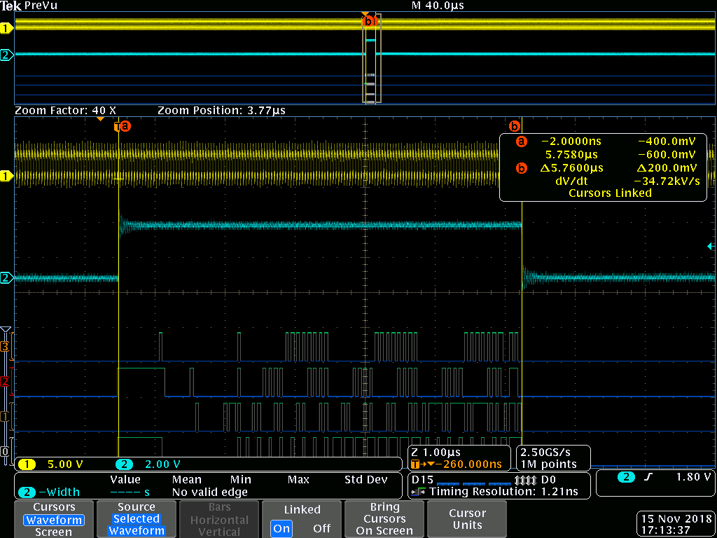
    The length of the flame is 64 byte including FCS. The time from rising edge to falling edge of TX_CTRL is 5760[ns]

    (5760 / 40 = 144[nibble] 144 / 2 = 72 [byte] = 64(frame size) + 8 (preamble + SFD))

    The register values are below.

    Address: Value
    0x00: 0x2100
    0x01: 0x794d
    0x02: 0x2000
    0x03: 0xa231
    0x04: 0x1e1
    0x05: 0x0
    0x06: 0x64
    0x07: 0x2001
    0x08: 0x0
    0x09: 0x300
    0x0A: 0x0
    0x0B: 0x0
    0x0C: 0x0
    0x0D: 0x401f
    0x0E: 0x0
    0x0F: 0x3000
    0x10: 0x5028
    0x11: 0x6f02
    0x12: 0x0
    0x13: 0x0
    0x14: 0x29c7
    0x15: 0x0
    0x16: 0x0
    0x17: 0x40
    0x18: 0x6150
    0x19: 0x4444
    0x1A: 0x2
    0x1B: 0x0
    0x1C: 0x0
    0x1D: 0x0
    0x1E: 0x2
    0x1F: 0x0
    0x32: 0xd1
    0x33: 0x0
    0x6E: 0x0
    0x6F: 0x0

    ============================================================================

    I tried 10Mbps transmission in both MII and RGMII mode. The result is same that I could confirm the packet in case of MII mode, and could not see packet in case of RGMII mode using Wireashark.

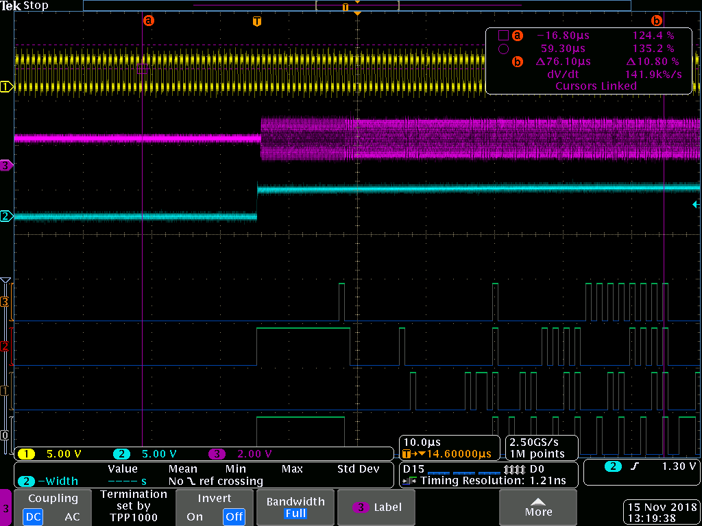
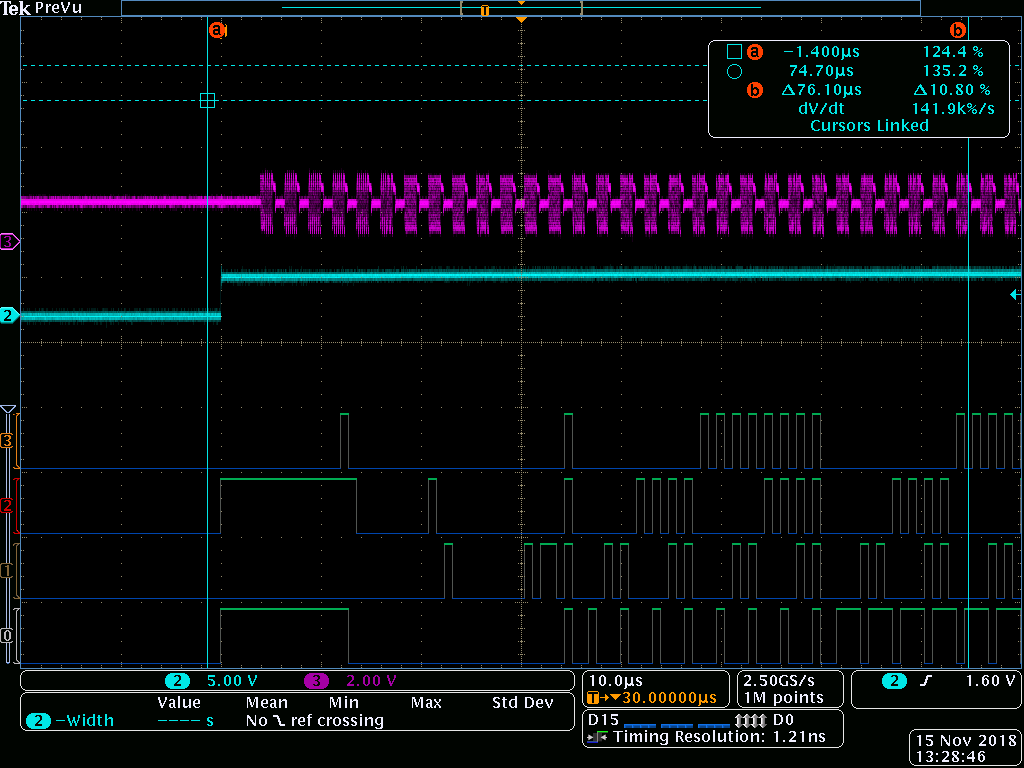
    I monitor the signal after Manchester coding (PHY to PHY signal). And found that the signal is different between MII mode and RGMII mode.In my understanding, since the speed is same, the PHY to PHY signal should be same in both mode. The pink signal in below image is the PHY to PHY signal.

    MII mode↓

    RGMII mode↓

    Is this providing any hint?

    Best regards,

    Tsunokawa

  • Hi Tsunokawa,

    Yes, this is a good hint.

    Because the signaling on the cable is different between MII and RGMII for the same data packet, we know there is an issue with the RGMII transmission.

    The repetitive nature of the symbol on the cable makes me believe the PHY is understanding the MAC's signaling as one of the reserved, or special symbols defined.  Can you look closely at the TX_CTL signal with relationship to TX_CLK.

    TX_CTL should be high only on the first rising edge of TX_CLK, and should remain high until the falling edge of TX_CTL when packet transmission is complete.

    The following table is from the RGMII standard.  TX_CTL is listed by a 2 bit vector.  The first bit is related to rising edge of TX_CLK, second bit is falling edge.

    For example, if TX_CTL is 0 on rising edge of TX_CLK, then 1 on falling edge of same TX_CLK cycle, you get one of the following reserved/error symbols transmitted.

    MII does not have this need to decode special indications because TX_ER, TX_EN are discrete signals.

    Best Regards,

  • Hi Rob,

    Thanks to your support, at last, I could see the packet in RGMII mode with Wireshark.

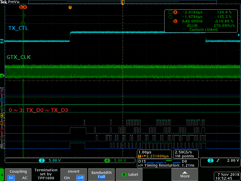
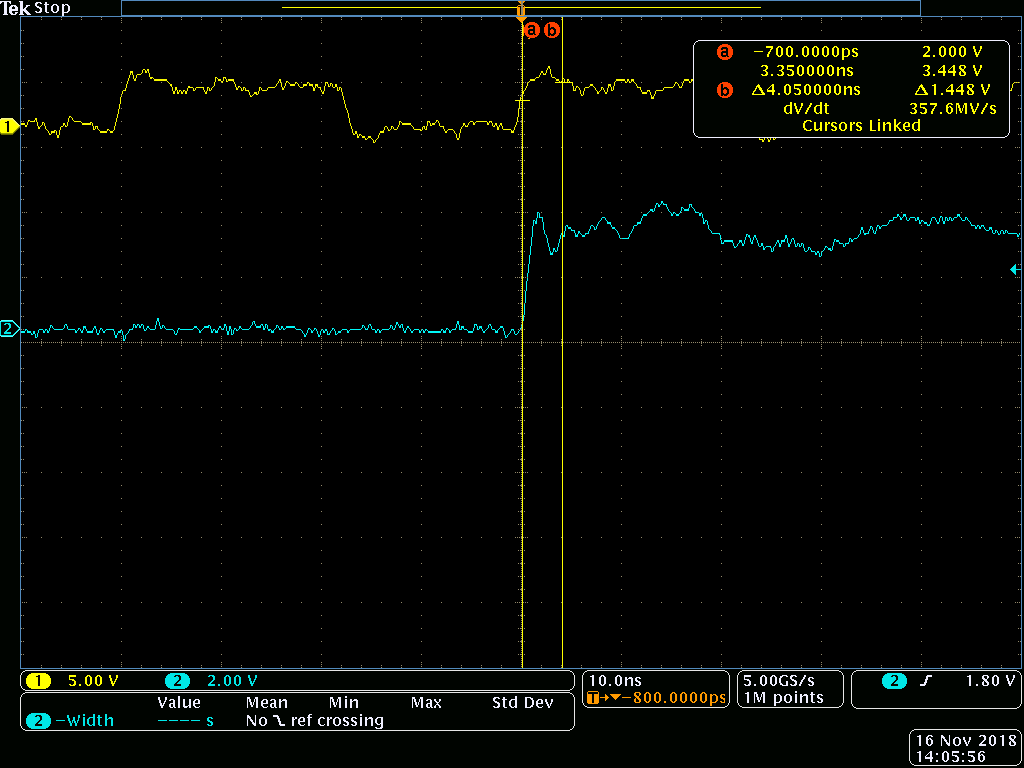
    I closely checked the rising of TX_CTL, as you suggested. Below is the timing of GTX_CLK (yellow) and TX_CTL (blue).

    It is possibly capturing 0,1 (rising, falling). With this timing, the transmission failed.

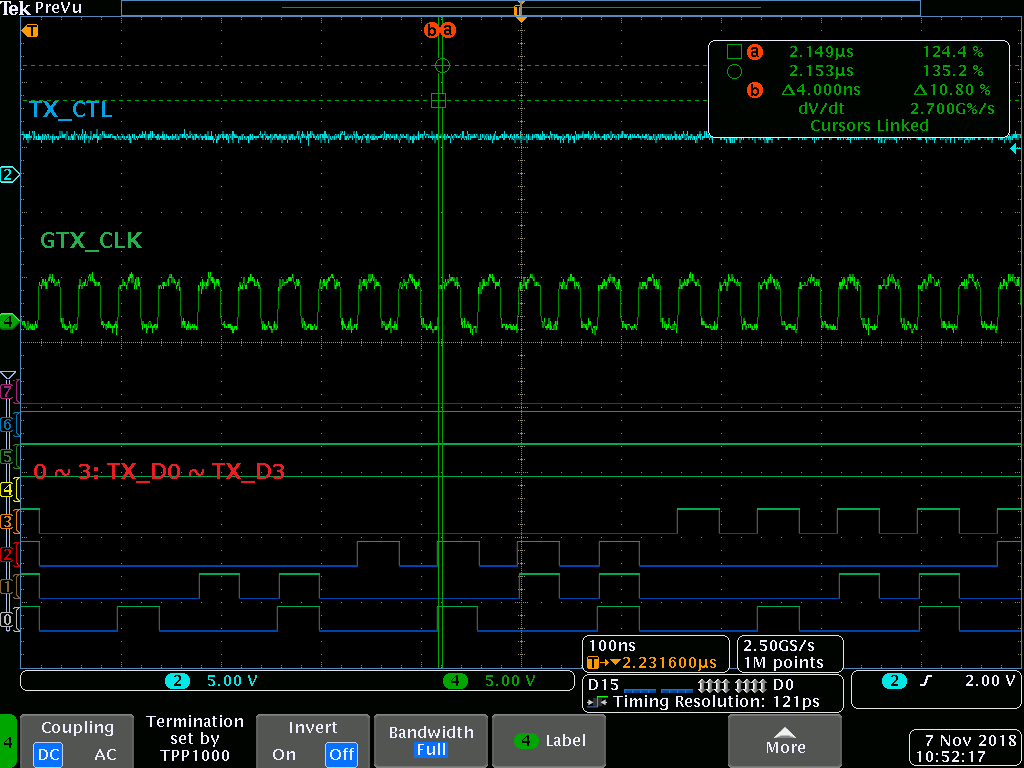
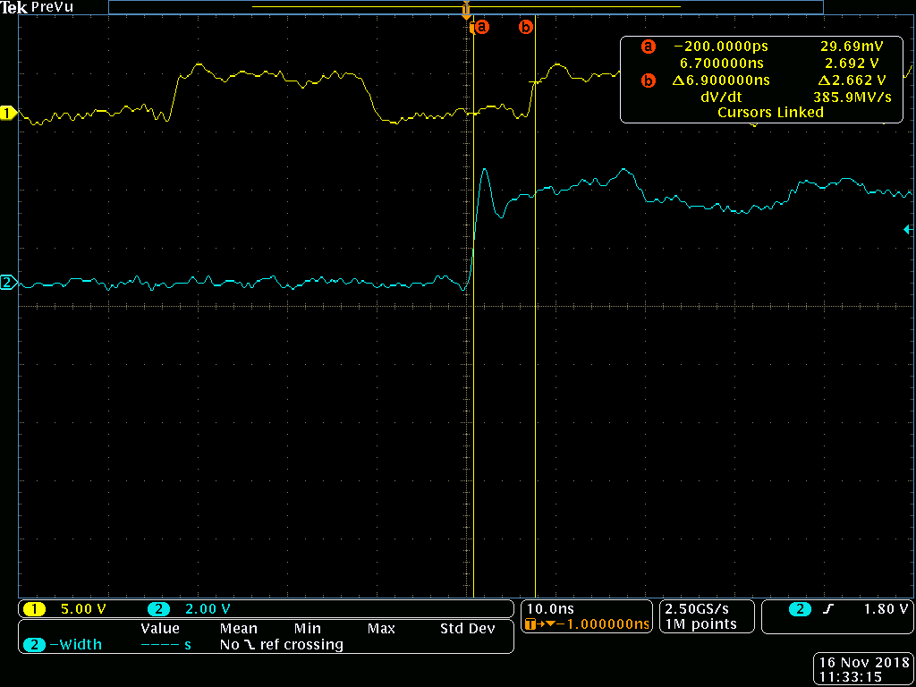
    Then I added external buffer circuit between MAC and PHY to delay GTX_CLK. After adding the buffer, the timing got below.

    And with this timing, I could catch the ether frame with the Wireshark.

    My question is that

    I originally set internal PHY TX delay as 4 [ns]. Shouldn't it help this issue?

    My delay circuit looks delaying GTX_CLK about 7 [ns]. 4 [ns] was not sufficient or something was wrong with my PHY setting?

    Best regards,

    Tsunokawa

  • Hi Tsunokawa,

    For the purpose of TX clock delay, register 0x32[1] = 1, and register 0x86[7:4] = 0xf should be enough delay(4 ns) to send edge aligned TX_CLK and TX_CTRL without problems. I am not sure why you are seeing issues here.

    Do you have source termination resistors on the TX lines for the FPGA? There appears to be a bit of overshoot and some ringing. It appears to be within spec of the interface, but may be causing some troubles. Can you share a schematic of the PHY?

    Best Regards,
  • Hi Rob,

    Thank you. 

    No, I don't have termination registers on TX lines. And It seems this is the cause of this issue. Absence of the registers seems to make my system very unstable.

    Today, I tried with register 0x32[1] = 1, and register 0x86[7:4] = 0xf, and I could see transmission succeeded. This had failed in the past. I think the differences are temperature and manual soldering. 

    And I tried with with register 0x32[1] = 1, and register 0x86[7:4] = 0xe, and I saw transmission sometime failed, and sometime succeeded.

    So, my system is very unstable probably because of the ripple on TX line.

    I'd like to conclude this issue with below.

    Rout cause: absence of termination register of TX line

    Solution: add termination register to TX line.

    Again, thank you very much for your solid support.

    Best regards,

    Tsunokawa

  • Hi Tsunokawa,

    I am pleased to hear your issue is identified and resolved!

    Best Regards,