This thread has been locked.

If you have a related question, please click the "Ask a related question" button in the top right corner. The newly created question will be automatically linked to this question.

DS80PCI402: Inquire SCH review, EVM request and spec question

Part Number: DS80PCI402

Hi Sir,

May I have your help for below items:

1. How could we apply DS80PCI402 EVM for verification?

2. Could you kindly help to review the SCH and provide your suggestion to us?

3. According to datasheet P.4, may I learn from you that why OUTB(Pin1-8) I/O type is I, but INB I/O type is O? 

4. May I learn from you the power consumption of DS80PCI402? 

5. If we would like to use external resistor to adjust EQ, do we need to configure to PIN MODE(ENSMB low)?

6. May I know the function of PIN 23 LPBK? For lookback mode testing?

7. If we didn't use EEPROM, could we leave PIN27 ALL_DONE floating?

Thank you for your kindly help.

Best Regards,

Edward Chen

EMP-PCI68-AA-V0.9.pdf


  • Hi Edward,

    1. The DS80PCI402EVM is designed for benchtop use with SMA cables.  It was not intended to be a means to do system verification.

    2a. The OUTA and OUTB pins should have 0.22uF AC coupling capacitors instead of resistors.

    2b. The resistors are not typically placed in series on the INA and INB pins.

    2c. Connect VIN to C6 + C7 and VCC3V3 only

    2d. Connect VDD to C1 - C5 only.  Do not connect VIN to VDD.

    2e. Recommend PRSNT is tied to DS80PCI402 and Endpoint.

    2f. For starting signal integrity settings. Recommend DEM = Level 4, EQ = Level 2

    3. It is a typo in the datasheet. OUTB is type "O" and INB is type "I".

    4. The typical power consumption is 660mW

    5. Yes if you want to use external pin configuration then ENSMB = 0.

    6. LPBK was mainly used for testing purposes, it does provide a "loopback" function, but the signal integrity is not as good as the normal path.

    7. Yes if no EEPROM is used pin 27 can remain floating.

    Regards,

    Lee

  • Hi Lee,

    Thank you for your comments, please refer below question:

    2a. The OUTA and OUTB pins should have 0.22uF AC coupling capacitors instead of resistors.

    E: In the layout, 0.22uF AC coupling cap should close to chip or connector?

    2b. The resistors are not typically placed in series on the INA and INB pins.

    E: So should we put 0.22uF cap in series on INA and INB pins?

    2d. Connect VDD to C1 - C5 only.  Do not connect VIN to VDD.

    E: Does it means we can connect all VDD pin together?

    2e. Recommend PRSNT is tied to DS80PCI402 and Endpoint.

    E: Could you kindly share more detail description about this part?

    3. It is a typo in the datasheet. OUTB is type "O" and INB is type "I".

    E: Do we have any schedule to revised datasheet?

    Please refer latest SCH and kindly share your comments for us.

    Thank you.

    Edward Chen

    emp-pci68-aa-v0.9-2018-11-8.pdf

  • Hi Lee,

    May I have your support on this case?

    Thank you for your kindly help.

    Best regards,

    Edward Chen
  • Hi Lee,

    Thank you for your comments, please refer below question:

    2a. The OUTA and OUTB pins should have 0.22uF AC coupling capacitors instead of resistors.

    E: In the layout, 0.22uF AC coupling cap should close to chip or connector?

    (Lee):  I prefer to see the coupling capacitor close to the connector.

    2b. The resistors are not typically placed in series on the INA and INB pins.

    E: So should we put 0.22uF cap in series on INA and INB pins?

    (Lee)  There needs to be one set of coupling capacitors between PCIe Rx and Tx.  Typically the coupling capacitors are placed on the same PCB assembly as the PCIe Tx pins.

    2d. Connect VDD to C1 - C5 only.  Do not connect VIN to VDD.

    E: Does it means we can connect all VDD pin together?

    (Lee): Yes all VDD pins (9/14/36/41/51) can be connected together.

    2e. Recommend PRSNT is tied to DS80PCI402 and Endpoint.

    E: Could you kindly share more detail description about this part?

    (Lee):  Since you are not using the PRSNT# signal on the CEM connection, I would tie the PRSNT pin on the DS80PCI402 device to GND. 

    3. It is a typo in the datasheet. OUTB is type "O" and INB is type "I".

    E: Do we have any schedule to revised datasheet?

    (Lee):  I do not have a schedule for the datasheet at this time.

    Please refer latest SCH and kindly share your comments for us.

  • Hi Sir,

    Could you please support check the Layout?

    Hugo

  • Hi Lee,

    May I have your help to review the layout?

    Thank you.

    T2352-IDXTM-8004_GF-PCIEconn_V0_9-181122_pm6.zip

  • Hi Hugo,


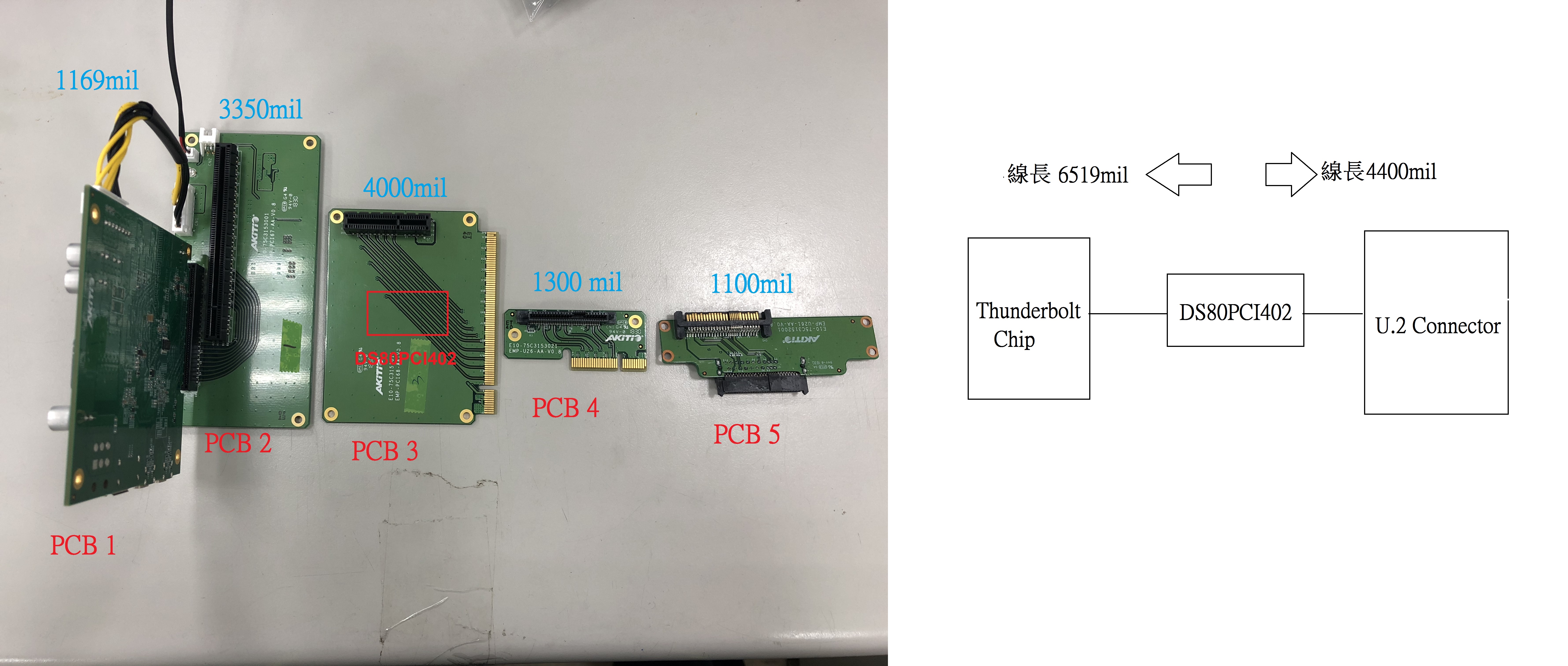
    Are you designing for 85 ohm impedance?
    Are the AC coupling capacitors 0402 size?

    Regards,
    Lee
  • Hi Lee,

    The Thunderbolt 3 Spec is 90ohm, so our customer is 90ohm impedance.
    The AC coupling is 0402 size.

    Hugo
  • Hi Hugo,

    90 Ohm impedance and 0402 size capacitors are a good combination.

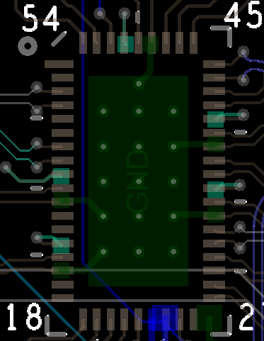
    I would rework the thermal pad vias into a more symmetrical arrangement to improve manufacturing.  Here is an example, you can cut down on the size of the VDD_2.5V moat, there is not a big need to connect the pins externally.

    Regards,

    Lee

  • Hi Lee,

    Do you know have customer used the DS80PCI402 on Intel thunderbolt titan ridge?

    Our customer verify this HW is only can be run the Intel thunderbolt alpine ridge.

    If we are uesd the titan ridge ths SSD card can't Being detected on NB. need Hot plug TYPE C cable to Redetect.

    Hugo

  • Hi Hugo,

    I do not know any details about the Intel Titan Ridge design or Alpine Ridge design.

    It makes sense that a hot plug cable would need to be used to redetect drive. 

    What mechanism is used by these designs to detect the SSD hot plug event?

    Thanks and Regards,

    Lee 

  • Hi Hugo,
    We don't know if this is the case. DS80PCI402 is a popular device and it is readily available on TI.COM.
    Regards,,nasser