This thread has been locked.

If you have a related question, please click the "Ask a related question" button in the top right corner. The newly created question will be automatically linked to this question.

TMDS442 initialization

Other Parts Discussed in Thread: TMDS442, THS7303

The TMDS442 DVI/HDMI switch has no provision for external reset. The datasheet specifies the state of internal registers on "power up". No specification of what constitutes "power up" is given. How low must the power supply go to assure proper resetting of the internal machine states? For how long?

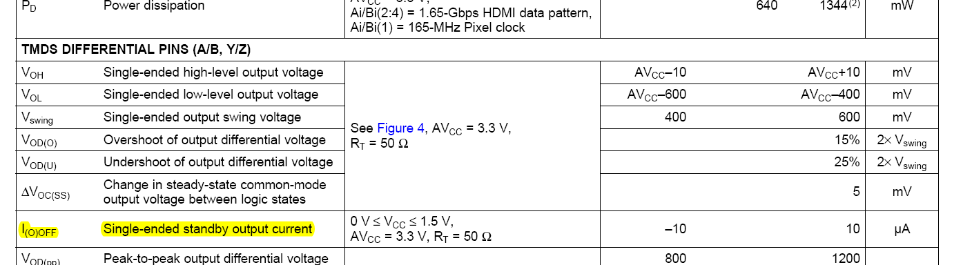
Many sources of DVI (NVIDIA cards) do not have a simple current sink to ground, they can supply current into an unpowered DVI input. There seems to be no isolation between the TMDS442 input terminations and VCC. How do you guard against current flowing into the VCC from the DVI input not allowing VCC to fall low enough to guarantee an adequate power-on reset? This has happened to me before, not just a theoretical worry. And I've had terrible experiences with some I2C video muxes from TI not working properly upon power-up.

Thank you.


Lance Garland

  • The only power on a DVI/HDMI cable input to an unpowered device would be from the 5V signal (TMDS signals are CML).  I am not aware of any issues on what you have described or anything else associated with this device.  i am not aware of any power-on reset for this device.  My understanding is that as long as the power rails are in ther operating range, the device is available for operation.

  • Thanks Ken,

    There absolutely are non-compliant DVI sources that can supply some milliamps of current into an unpowered device, I've seen this on some video cards and right now my Quantum 802F video generator on my bench causes 2.4V to appear on the inputs to my unpowered Silicon Image DVI receiver causing the +3.3V to float up to ~2volts. To make the logic in that receiver work properly a proper reset has to be supplied. This issue has caused me to spin boards before, I'm not prepared to ignore it.

    My poor experience with the THS7303 with its need for special treatment after power-up has made me very wary of "analog" chips with I2C interfaces which claim no need for reset. The TMDS442 absolutely has some sort of a state machine inside, isn't there some sort of internal scheme for setting all of the flip-flops? Is TI guaranteeing that I can allow the power to fall from 3.3V to 1-2V and back to 3.3V and everything will be ok? I can imagine that could be the case if you had a good internal power-on reset circuit. If not then what is the spec?


    Lance

  • Lance,

    With the age of this device, we will need to get the design team involved to get to the answer you are looking for.   Please allow some time for this activity.

  • Lance,


    The TMDS442 has an internal POR around 2.2 V with a 200 mV hysteresis.

  • Thank you Ken.


    Lance

  • Lance,

    We are observing power-up issues with the TMDS442 as well. Our problem is that the monitor doesn't properly initialize out of power-up, which we assume is DDC related. If we switch away from the selected source and then back, things seem to work much better. The lack of documentation at the power-up makes this a tough issue to isolate. An external reset sure would be nice! Were you able to address your power-up woes? 

    Also, we are seeing the same problem with the backfeeding of Vcc across numerous systems. However, strangely, in our situation, this seems to help the power-up issue - I'm assuming that this is because the TMDS442 isn't actually powering down.

    Any insight that you can provide would be appreciated...

    Thanks!

    -Rod

  • I don't use the DDC switching ports of the TMDS442. I've always run dedicated DDC EEPROMS (24c02s) off of a separate +5V supply that is derived from diodes connected to the +5V_DDC line and my system 5V. I have a separate EEPROM connected for each DVI connector. It wasn't clear to me what the TMDS442 would do with no +3.3V power but with DDC still connected.

    The +5V on the DVI connector is there so that you can have proper DDC communication without display power so I always take advantage of it. It greatly reduces power-cycle weirdness. I doesn't really sound like you have a reset issue in the TMDS442. My system has been working fine.

  • I have not seen any issue with power-up because of a TMDS442.   What is the HPD doing from the receiver during the power up?  If it is driven high, it is possible that the source is seeing the change and attempt to read the EDID.  By the way, where is the EDID?  Is it on each of the inputs or are you placing the EDID on the receiver side of the switch?  


    As far as back feeding, the TMDS442 has a spec of less than 10 uA of leakage (Ioff) from the TMDS signals.  Where are you seeing the leakage?


  • Ken,

    Our circuit is configured exactly as shown in the Dual-Link 2-to-1 Switch Configurations on Page 31 & 32 of the datasheet. We may have the mistake of assuming that page was an accurate reflection of what needed to be done. It sounds like more support is required that what is shown to handle the EDID data?

    -Rod


  • I took a quick look again at the diagram and do not see an indication of the EDID being implemented.  Does this mean your design does not include an EDID?  The intent of the diagram is to show how the TMDS442 is configured to support the dual link DVI and not intended to be a full system diagram.  Sorry for the confusion.

  • Hmmm...We connected the DDC as shown.  So from Source 1 to SDA1/SCL1 and from Source 2 to SDA3/SCL3.  SDA_SINK1 & SCL_SINK1 go to the display, which supports  EDID.  The datasheet reads like the chips performs a pass thru.  Is this not the case? Or is the approach that Lance outlined required?

    -Rod

  • My recomendation is what Lance has done and put the EDID at the input powered by the HDMI 5V (this will always be a cleaner solution).  This allows the source to read the EDID without the receiver to be powered or having to manage the HPD in conjuction with the device power and power to the EDID.   As soon as the source gets the HPD signal, it will start attempting to read the EDID.  If our device or the EDID is not up, then it will fail the EDID read, and possibly setup the wrong signal, or stop trying.  

  • Interesting thread. I've included On Semi's CM2031/CM2030 to prevent the backfeeding problems giving a false HPD signal and other problems. Am I kidding myself? I didn't want to tie an EDID to each input as the outputs may be connected to different sink types.

    Also, I've searched and searched the parts data sheet but cannot find the electrical connection to the thermal pad. Is it ground?

    Thanks

    Bill  

  • Bill,

    After doing some checking into the datasheet, the IC uses TI's PowerPAD technology. There are several guideline and reports detailing how to properly implement the PowerPAD devices. please see these links:

    http://www.ti.com/lit/an/sloa120/sloa120.pdf

    http://www.ti.com/lit/an/slma002g/slma002g.pdf

    http://www.ti.com/sc/docs/msp/papers/1998/smi.pdf

    Section  "2.2 Copper Areas" in the first pdf mentions that "The thermal pad is usually tied to ground".

    Regards

    Colin