This thread has been locked.

If you have a related question, please click the "Ask a related question" button in the top right corner. The newly created question will be automatically linked to this question.

DS125DF410: Please kindly help us advise how to debugging to eliminate the bit error, thanks!

Part Number: DS125DF410
Other Parts Discussed in Thread: SIGCONARCHITECT

Dear TI experts,
I have a customer focus on high speed communication equipment, and choose TI retimer DS125DF410 to realize reliable data transmission,first time to use frtimer chip, so there have some technical need your great support, there have two question need help give some advice to go next step, thanks very much!
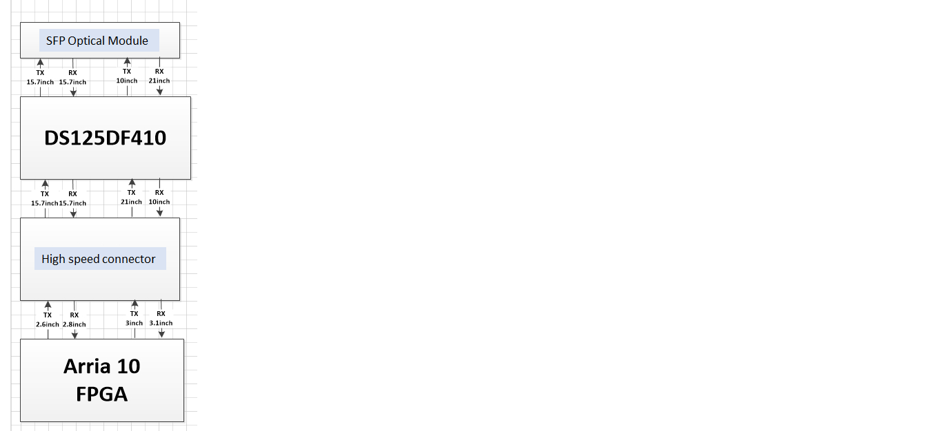
1) How to debugging can eliminate the bit error? If have impact where place the retimer? I place the retimer module in the middle of the optical module and high speed connector, self-loop bit error rate about 10^-2/-3, when I remove the retimer near to optical module(about 9.8inch), optical module TX  and end board RX bit error rate about 10^-11/-12, but optical module RX and end board TX have no bit error appear.If have  directly related with position or What factors are relevant?


2)Test board use communication frequency is 10.3125Gbps, and the product actual frequency is 12.5Gbps, would you please kindly help advice how to configuration register can quickly achieve it?


3) I found DS125DF410 have PRBS generator but have no checker, how to achieve self-detection?

Best regards

Jacking


  • Hi Jin,

    DS125DF410 CTLE gain is about 34-db at 5GHz or 10Gbps and transmit de-emphasis is 15-dB. Given these two criteria, we have to position DS125DF410 device such that it meets these two requirements with some margin. Additionally, DS125DF410 should be placed within 6-8 inches of the SFP module. If the device is placed at a shorter distance then there could be some over-equalization. Given these constrains, please below note responses to your questions: 

    1). DS125DF410 should be placed about 6 to 8 inches away from SFP optical module.

    1a). Given this, RX and TX to optical module meets DS125DF410 two requirements that I noted earlier.

    1b). From Arria10 FPGA to DS125DF410: Again this is within DS125DF410 CTLE requirement(34-dB).

    1c). From DS125DF410 to the Arria10 FPGA: Please confirm Arria10 FPGA CTLE has at least 14-16dB gain at 5GHz.

    2a).  DS125DF410 Uses SigconArchitect GUI. You can use this software in demo mode, setup 12.5GHz VCO frequency, and it calculates register settings for 12.5Gbps. 

    2b). Or please note table 2 of the DS125DF410 data sheet. In this table, it shows register settings for 12.5Gbps(PROP3 or Interlaken 1). All you have to do is to set reg 0x2F based on this table settings.

    3). Please note section 7.5.10 Overriding the Output Multiplexer of the data sheet where we discuss register settings to enable PRBS generator. For PRBS checker you can use external BERT. Device doesn't have onboard PRBS checker.

    Regards,,nasser