This thread has been locked.

If you have a related question, please click the "Ask a related question" button in the top right corner. The newly created question will be automatically linked to this question.

DS90UB913A-Q1: Could not establish BCC (i2c) communication between the 913 and 914 on the Spectrum Digital kits

Part Number: DS90UB913A-Q1
Other Parts Discussed in Thread: ALP

We are using the boards from Spectrum Digital below, to evaluate FPD LINK III

http://www.spectrumdigital.com/fpd-link-iii-deserializer-board/

http://www.spectrumdigital.com/fpd-link-iii-serializer-board/

These boards use the 913 and 914 respectively.  With the Total Phase Aardvark controller, we can communicate with the 914 by reading the following correct value:

- SER ID (offset 0x06 of the 914) has the auto-loaded value 0xB0 (wihch is 0x58 left shifted by 1-bit)

Next we would program offset 0x07 of the 914 with a SER alias value of 0xB2 (wihch is 0x59 left shifted by 1-bit).  We can read this register back properly.

We then start reading offset 0x0 of the 913 using the device address of 0x59, but there is no response.

Next we try reading offset 0x0 of the 913 using the device address of 0x58, also no response.

We try using the TI utility Analog LaunchPad to do the same thing, still no response from 913. 

Below is the screenshot of how it looks for us when using the utility

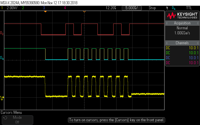
We have the waveforms of the scope probing at the i2c SDA (red plot) and SCL (blue digital version, yellow analog version) of the 914 below.  It shows when we try to talk to device 0x59, the i2c clock is being stretched, and we don't get acknowledge bit.  The link then goes to timeout.

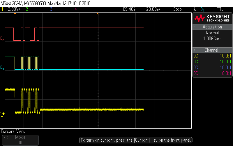
Zooming in of the same plot below

What is the cause of no response of 913?

  • Could you verify if there's LOCK between 913-914. 914 register 0x1C bit 1 and bit 0 should be 1 if the devices are locked. 

    Could you also verify that 913 is correctly strapped to address of 0xB0 by checking the voltage divider for IDx pin?

    Best Regards,

    Charley Cai

  • Hi Charley,

    On the SER 913, the Rid resistor (Table 6 in the 913 datasheet) has the value of 0Ohm. This gives the device address 0x58 in 7-bit, or 0xB0 in 8-bit. This matches the value we read from the DES 914 at offset 0x06.

    On the SER 913, the Rmode resistor has the voltage (Table 2 in the 913 datasheet) has the value of
    0.568V, which means Rmode has the value of roughly 4.75kOhm. This configures the 913 to be in the external OSC mode. The OSC freq on the board is 48MHz, confirmed by a scope. However the 913 has no output clock at pin 17 (GPIO/CLKOUT). What would be the cause of this?
  • Can i get an register dump for both the 913 and 914? You could use Analog LaunchPad to save register settings into a file.

    Best Regards,
    Charley Cai
  • Please see below for the register settings, using an Aardvark controller connected to 914

    FPD Link Register Readout 914
    Register Display - ALP Nano 1 - DS90UB914A, Connector 1

    Register    Data    Name
    0x0000    0xC0    I2C Device ID
    0x0001    0x04    Reset
    0x0002    0x00    General Configuration 0
    0x0003    0xE9    General Configuration 1
    0x0004    0x00    EQ Feature Control 1
    0x0005    0x00    EQ Feature Control 2
    0x0006    0xB0    SER ID
    0x0007    0xB2    SERAlias
    0x0008    0x00    SlaveID[0]
    0x0009    0x00    SlaveID[1]
    0x000A    0x00    SlaveID[2]
    0x000B    0x00    SlaveID[3]
    0x000C    0x00    SlaveID[4]
    0x000D    0x00    SlaveID[5]
    0x000E    0x00    SlaveID[6]
    0x000F    0x00    SlaveID[7]
    0x0010    0x00    SlaveAlias[0]
    0x0011    0x00    SlaveAlias[1]
    0x0012    0x00    SlaveAlias[2]
    0x0013    0x00    SlaveAlias[3]
    0x0014    0x00    SlaveAlias[4]
    0x0015    0x00    SlaveAlias[5]
    0x0016    0x00    SlaveAlias[6]
    0x0017    0x00    SlaveAlias[7]
    0x0018    0x00    CRC Errors THRESHOLD
    0x0019    0x01    CRC Errors THRESHOLD
    0x001A    0x00    CRC Errors
    0x001B    0x00    CRC Errors
    0x001C    0x03    General Status
    0x001D    0x33    GPIO[1] and GPIO[0] Config
    0x001E    0x33    GPIO[3] and GPIO[2] Config
    0x001F    0x04    Mode and OSS Select
    0x0020    0xFE    BCC Watchdog Control
    0x0021    0x17    I2C Control 1
    0x0022    0x00    I2C Control 2
    0x0023    0x00    General Purpose Control
    0x0024    0x08    BIST Control
    0x0025    0x00    BIST ERROR COUNT
    0x003C    0x00    OSC OUT DIVIDER SEL
    0x003F    0x10    CML OUTPUT ENABLE
    0x0040    0x82    SCL High Time
    0x0041    0x82    SCL Low Time
    0x0042    0x00    CRC Force Error
    0x004C    0x00    SEL Register
    0x004D    0x20    AEQ Test Mode Select
    0x004E    0x0F    EQ Value

  • Please see below for the register settings, using an Aardvark controller connected to 913

    FPD Link Register Readout 913
    egister Display - ALP Nano 1 - DS90UB913A, Connector 1

    Register Data Name
    0x0000 0xB0 I2C Device ID (0x00)
    0x0001 0x30 Power and Reset (0x01)
    0x0003 0xC5 General Configuration (0x02)
    0x0004 0x80 Reserved
    0x0005 0x00 Mode Select (0x03)
    0x0006 0x00 DES ID (0x04)
    0x0007 0x00 DESAlias (0x05)
    0x0008 0x00 SlaveID (0x06)
    0x0009 0x00 SlaveAlias (0x07)
    0x000A 0x00 CRC Errors (0x08)
    0x000B 0x00 CRC Errors (0x09)
    0x000C 0x11 General Status (0x0A)
    0x000D 0x55 GPIO[0] and GPIO[1] Config (0x0B)
    0x000E 0x35 GPIO[2] and GPIO[3] Config (0x0C)
    0x000F 0x00 I2C Master Config (0x0D)
    0x0010 0x17 I2C Control (0x0E)
    0x0011 0x82 SCL High Time (0x0F)
    0x0012 0x82 SCL Low Time (0x10)
    0x0013 0x00 General Purpose Control (0x11)
    0x0014 0x03 BIST and DOPL Control (0x12)
    0x0016 0x80 RESERVED
    0x001E 0xFE BCC Watchdog Control (0x1E)
    0x0023 0x00 RESERVED
    0x0029 0x06 Reserved
    0x002A 0x00 CRC Errors (0x18)
    0x0035 0x09 PLL CLK OV (0x24)
  • We still cannot establish i2c communication with the 913, through the 914, as stated in the first post above.

    Are the register settings properly configured for communication between 914 and 913?
  • Please note that this thread is not resolved yet.
  • Understand. I am looking into the register dump and will reply within a day.

    Charley
  • Other than the register mappings, we get the XCLK out from the 913 by doing cycle power of the 914 card. The oscillator on the 913 card is 48MHz. However, the XCLK out of the 913 is not 24MHz (half of the OSC), but it is 25MHz and it has a lot of jitter. What could be causing the XCLK to not lock?
  • From the register reading, it looks like there is no back channel communication from 914 to 913.
    A few contributing factors could be
    1. What kind of cable are you using and how long?
    2. Could you verify if there’s back channel signal output from the 914 by probing?
    3. I see that on the spectrum digital board, there’re multiple 914 devices. Does this issue happen for all of them or just one 913-914 pair.
    4. Are you using the PoC network on the 914 board to power 913? And was there any modification done to the PoC network?

    Best Regards,
    Charley Cai
  • Also, since 913 is not getting back channel communication, it is in incorrect mode.
    Try to program 913 locally by setting register 0x05[5] to 1 and 0x05[0] to 1 to force 913 into 10bit mode. Please check if this helps with XCLK


    Best Regards,
    Charley Cai
  • 1. The cables being used are the Pasternack 50Ohm coax, 36-inch length, part number PE38746Z-36.  The website for this cable is www.pasternack.com/fakra-jack-fakra-jack-pe-c100-cable-assembly-pe38746z-60-p.aspx

    2. When we probe the pin RIN1+ (pin 32) of 914, there is some waveforms, but we don't know if the BCC is working from the 914 to 913.  Is there a more definite place to probe?

    3. Yes, this issue happens the same for the few channels that we try (Ch1, Ch2, Ch3, Ch5).

    4. Yes, the PoC network on the 914 board is used to power the 913 board over the cable.  We did not modify the PoC network on the 914 board.  We did remove the Infor EEPROM (U3) on the 914 board, to solder the wires for i2c on the Aardvark controller.

  • We probed SW1 on the 913 board, the voltage is 0.568V, i.e., the MODE register is 4.75kOhm.  This means the 913 is in 10-bit mode.  Not sure why the XCLK is 25MHz, but not 24MHz yet.