This thread has been locked.

If you have a related question, please click the "Ask a related question" button in the top right corner. The newly created question will be automatically linked to this question.

DP83822HF: MDC and MDIO connection

Part Number: DP83822HF
Other Parts Discussed in Thread: USB-2-MDIO, MSP430F5529

Hi Support team,

I have a problem to connect with the microchip switch IC  ( KSZ8863 )。 We would like to know if the PHY IC ( DP83822HF ) config as RMII interface as below table mentioned.

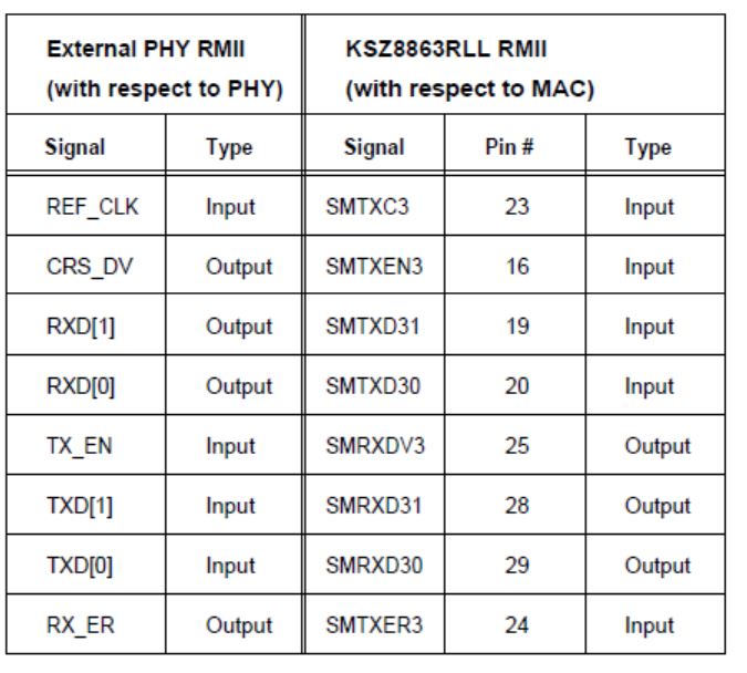
if no connection of MDC and MDIO pins? Does the PHY IC  can work fine or must be connected those pin for control.

And 


How about the below configuration for RMII interface is correct or not

Pin         Mode          RH                                RL
COL          4              open ( NC )                   open ( NC )
RX_D0      1              open ( NC )                   open ( NC )
RD_D1      1              open ( NC )                  open ( NC )
RX_D2      1              open ( NC )                  open ( NC )
RX_D3      1              open ( NC )                  open ( NC )
LED_0       4              open ( NC )                 open ( NC )
CRS          2              13 kOhm                      1.96 kOhm
RX_ER     4               open ( NC )                  open ( NC )
RX_DV     4            2.49 kOhm                      open ( NC )

Regards

Kelvin Lo

  • Hi Kelvin,

    The table connections you show above are correct between the KSZ and 822 are correct for RMII.

    The DP83822HF does not require MDIO/MDC for operation, the PHY can be configured through hardware bootstrap only.

    Also, the table for bootstraps above is correct if the MAC you are connecting to does not have internal pulls.
    However, looking at the KSZ datasheet the MAC pins have internal pulls, which will fight the internal pulls of the PHY as well as the external pulls.
    Please compensate accordingly to get the correct threshold voltage as found in the Electrical Char table within the DP83822 datasheet.

    SMTXER3 (RX_ER) has an internal PU
    SMTXD31 (RX_D1) has an internal PU
    SMTXD30 (RX_D0) has an internal PU
    SMTXEN3 (CRS_DV) has an internal PU
  • HiRoss,

    After modified the pull-up and pull-down resistor as below table, but the problem cannot be solved.

    We would like to know for the RMII sleave mode,  Are both RX_ER and  CRS_DV is optional connect to  MAC pin?

    We would like to know the 83822 chip what is time to read the bootstrap pins after reset from low to high?

  • Hi Support team,

    We did measure the voltage of the RX_DV ( pin26 ). it should be closed to VDDIO, But we measured the pin is  0V and force the reset pin to low, this pin voltage will change to 2.7V . However,  this pin should  be config the 50MHZ clock and RMII mode. Please advise with thanks!

    Regards

    Kelvin Lo

  • Hi Support team,

    When we set the bootstrap pins voltage by pull up and pull down reisitors, we measure the strap voltage is always is 0V, except pin 17 while providing the power to chip. But forcing the Reset to low, then can measured the strap voltage as above table mentioned. Is it normal?

    Regards
    Kelvin Lo
  • Hi Kelvin,

    Only when the PHY is in POR or RESET, will the pin be sampled.
    RESET is an active LOW, which makes sense that you see the correct voltage when RESET is LOW.
  • Hi Ross,

    1. We would like to know when the PHY set as RMII slave mode,   Does need to connect both RX_ER and  CRS_DV  to the MAC IC ?

    2. How to check the MAC to PHY connection is the right connection or not? any method or tools can be used?

    3. Until now, it is  still not working, there is no signal coming from pin 9 to pin12  ( currently no physical connection to the router, that mean those pins are open )

    Please advise with thanks!

    Regards

    Kelvin 

  • Hi Kelvin,

    The PHY is configured for RMII operation after POR/RESET is complete.
    RX_ER is optional. CRS_DV is used for RMII. What version of RMII are you using?
    The PHY supports both, but it is good to check which one your MAC supports.

    You can use USB-2-MDIO tool for debug. This will give you register access.
    Please blue wire to MDIO/MDC using the MSP430F5529 launchpad.

    www.ti.com/.../USB-2-MDIO

    Please have a look at this app note: www.ti.com/.../snla266.pdf