This thread has been locked.

If you have a related question, please click the "Ask a related question" button in the top right corner. The newly created question will be automatically linked to this question.

SN65LVDS31: SN65LVDS31 enable state definitions & differentiation

Part Number: SN65LVDS31


Hi,

  1. I am looking at TI part SN65LVDS31 now. The datasheet page 3, Table 1, Enables column did not state clearly between G and (invert G). Could you please help to clarify on this item

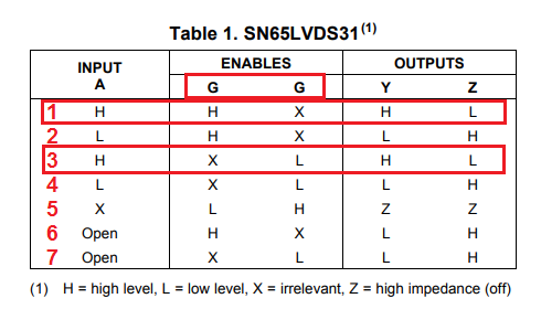
  1. Seems like configuring the enables as row 1 or row 3 as per table above yield the same outcome too. Is there any difference between configuration 1 & 3?


  • Hello Leo,

    Sorry about this typo in the datasheet and thanks for bringing it to our attention. In the table, the G on the right should be /G (invert-G). The actual functionality is clarified in the functional block diagram on page 14 in the datasheet.
    Rows 1 and 3 yield the same output since in both cases the device is enabled and the input is High. What this says is that if G is high OR if /G is low, then the output is enabled and reflects the input.

    Regards,
    Yaser
  • Hi Yaser,
    Thanks for the clarification & quick response, appreciate it if this can be updated onto datasheet to avoid confusion by customer in the future.

    Regards,
    Leo