This thread has been locked.

If you have a related question, please click the "Ask a related question" button in the top right corner. The newly created question will be automatically linked to this question.

HVDA553-Q1: what is the reason of HVDA553-Q1 Pin6 Pin7 short to GND?

Part Number: HVDA553-Q1
Other Parts Discussed in Thread: TCAN1042H-Q1, TCAN1042-Q1

Hi ti team,

     HVDA553-q1 used in car about 1 year,then the end customer find Pin6(canL),Pin7(canH) short to Pin2 GND. resistor about 47K and 23R.

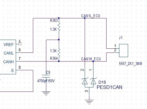
the sch is below.

    question:

1,Voltage range at bus terminals(CANH,CANL) is -27V to 40V, these pins if have test standard to check Auto car have been over this voltage?

2, help us check below SCH if have problem?

  • Hi Jimmy,

    The 47-kOhm resistance does not sound unusual, but the lower 23-Ohm resistance does suggest damage to the pin. The root cause for this is typically electrical overstress, which could occur from a variety of factors such as sustained voltages greater than the absolute maximum rating of a pin or via transient over-voltages like electrostatic discharge. Is possible either of these conditions occurred during operation (or any time after the unit was installed)?

    The schematic topology looks OK, but we would need to know the component values to be able to give any more detailed feedback. I did notice that you use a protection diode (D18) on teh CANH/CANL lines, and these are typically effective at reducing transient overstresses. It is important for the diode specifications to align with the transceiver's maximum supported ranges, though. You can read more about how to pair a TVS diode with an interface transceiver in this blog:

    e2e.ti.com/.../how-to-choose-a-tvs-diode-for-rs-232-rs-485-and-can-based-on-voltage-ratings

    Regards,
    Max
  • Hi Max,

         Sorry for delay

    Pls refer the detailed SCH

  • Hi Jimmy,

    Thanks for the info. I see PESD1CAN is used for transient protection. This is usually a good choice for CAN buses, but since the HVDA551 pin voltage rating is -27 V to +40 V, there is still some risk of overstress since the diode's peak clamping voltage is +/- 40 V (for transient currents up to 1 A) or +/- 70 V (for transient currents up to 3 A). My guess is that this system may have experienced one of these higher-current stresses and the voltage on CANH/CANL became large enough to damage the transceiver.

    If you wanted to design the system to be able to tolerate these kinds of stresses, you could look at using a TVS with a lower clamping voltage (like SM712) or a transceiver with a wider pin voltage rating (like TCAN1042-Q1 or TCAN1042H-Q1).

    If you wanted more information about the nature of the failure, you may want to work with your distributor or local sales contact on processing the device for failure analysis.

    Please let me know if you have any further questions.

    Regards,
    Max