Because of the holidays, TI E2E™ design support forum responses will be delayed from Dec. 25 through Jan. 2. Thank you for your patience.

This thread has been locked.

If you have a related question, please click the "Ask a related question" button in the top right corner. The newly created question will be automatically linked to this question.

TUSB4020BI: Bus powered circuit

Part Number: TUSB4020BI

Hi

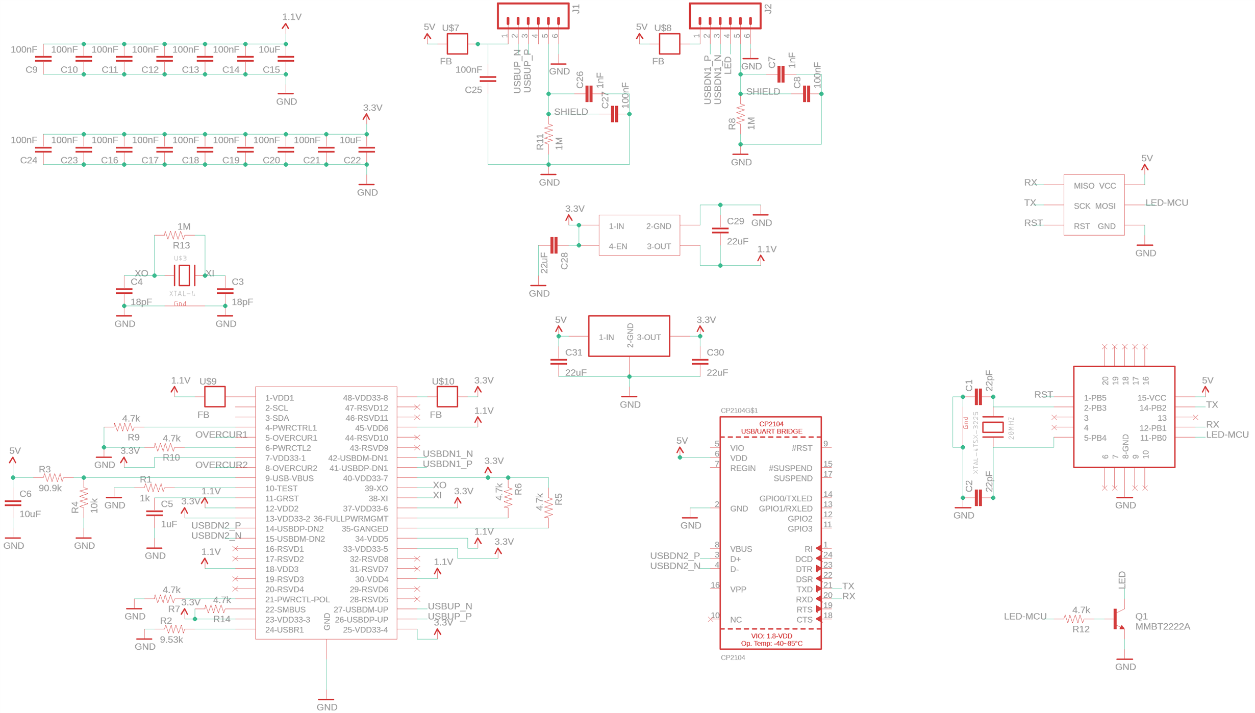
I'm trying to use the TUSB4020 in a circuit that has a webcam and a USB-serial chip (CP2104) connected to the 2 downstream ports. The CP2104 is connected on the same PCB and the webcam is connected via a soldered wire.

I have been following the example circuit, with a few tweaks to suit my application, but I cannot get the USB hub to work correctly with Windows. Whenever I connect it, Device Manager says the Device Descriptor Request failed. I've tried various driver uninstallations and resets, but no luck. I'm wondering if it has something to do with my circuit.

I'm not using external power, and understand about the device not meeting USB spec, this is just for a proof of concept prototype.

I have the following:

SMBUS pulled HIGH via 4.7kR

PWRCTL1 & PWRCTL2 pulled LOW via 4.7kR

GANGED & FULLPWRMGMT pulled HIGH via 4.7kR

Also, I'm a little confused about the current draw. When I connect all the 100nF capacitors at the VDD and VDD33 pins, the current draw at switch on is 360mA, but without those capacitors connected, it is just 108mA. Do you have any idea about why this is? The way I have the circuit configured is that the 3.3V regulator powers the 1.1V regulator. I have tried delaying the 1.1V switch on time by putting an RC on the enable pin of the 1.1V reg and also increasing the value of the capacitor connected to GRSTz, but these don't seem to have an effect on the current draw.

Any help appreciated.

Thanks

Laurence

  • Hi Laurence,

    Can you try powering on the system and doing a manual reset (short GRSTz low briefly)? That will help determine if this is a power up configuration issue or not. Another thing to check: DP / DM routing. I see that one connector has DM on pin 2 and the other has it on pin 3. Are these custom connectors? I would not expect the pin number to change for DM and DP. The last thing to check would be the ground pad connection. The thermal pad under the device is the main ground connection, if there is inadequate solder under the device it will not function as expected.

    Regards,
    JMMN
  • Hi

    Thanks for the response.

    So I have tried manually resetting the TUSB4020 as you described, but it is still not connecting properly. Once reset it connects but Windows says the device descriptor failed still. I noticed that when I pull the reset pin low, the current draw goes up to 240mA, from 40mA when in normal connected mode.

    As for the USB connections, it is not actually using a connector. There are wires soldered into the PCB coming into the upstream facing port and also going out to the webcam on downstream port 1. The device is meant as a hard wired device. I agree though that there is no need for them to be wired in different orders and I guess it would just caused potential confusion, so I'll change that. Thanks for pointing it out! But either way, I am currently testing this device without anything connected to either of the downstream ports. I am breadboarding it with neither the CP2104 or the webcam connected.

    As for the ground connection, I'm fairly sure there is a ground connection. The solder has melted in the vias and I don't have any shorts pins any of the pins and ground. Do you have any recommended way to test the quality of the soldered connection between the thermal pad and the PCB?

    Thanks
  • Hi Laurence,

    Yes, I would expect power consumption to go up in reset since the part is in an undefined state.

    A few more debug suggestions:

    1. Download and install usbview.exe (Microsoft tool) and see what descriptors are actually reported.

    2. Check the DP and DM lines on the upstream port - confirm that DP is high when the hub is not working.

    3. The easiest way to quickly check the thermal pad connection is to manually press the TUSB4020 to the PCB and see if the behavior improves.

    Regards,

    JMMN

  • Hi JMMN

    Thanks for getting back. Sorry for the delay, but I had to work on some other projects so couldn't work on this immediately.

    Anyway, pleased to say the problem has been sorted. It's all working fine now. When I wrote the previous post I had the TUSB4020 chip soldered onto a DIP breakout board and everything connected up on that on a breadboard. Whilst I triple checked that everything was wired according to the schematic I guess there must have been some ropey wiring somewhere. When I got the PCBs in that I had designed and soldered everything up, it worked fine.

    I used the USB device tree viewer which is based on the Microsoft code, but is fully compiled.

    Also, I don't know your opinion, but I found as a way to test the quality of the connection between the pad underneather the chip and ground, pins 28, 29, 31 & 32 seem to all be connected to ground. They are marked as reserved in the datasheet but I got good continuity.

    Many thanks for the help.

    Laurence