This thread has been locked.

If you have a related question, please click the "Ask a related question" button in the top right corner. The newly created question will be automatically linked to this question.

DS90C387: LVDS out data bit shift

Part Number: DS90C387
Other Parts Discussed in Thread: AM5728, ,

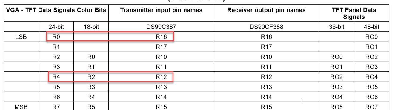
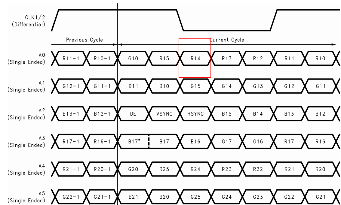
Hi, we are troubleshooting on one project using DS90C387 to drive a 1920*1080 LCD, the LCD requires 2 set of LVDS channels, thus the DS90C387 is set at single to dual mode. The input PCLK is set at 120MHz(2 times as LCD CLK 60MHz). The RGB input data is 24-bit from processor AM5728.

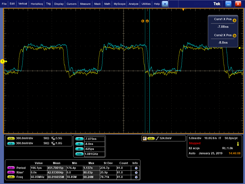
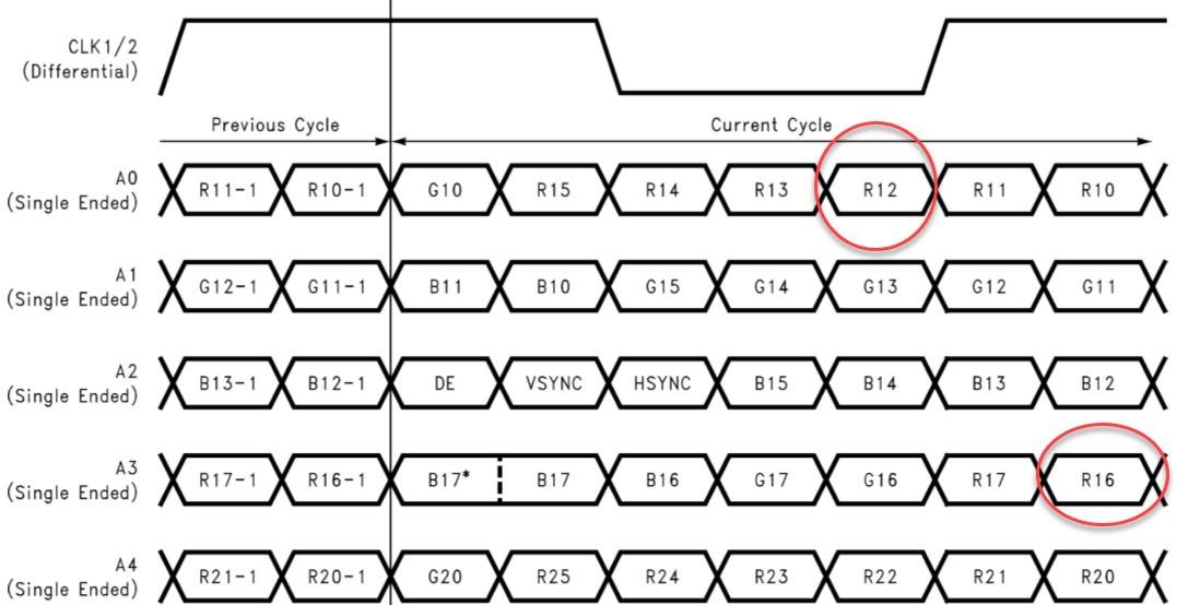
There is something wrong on the LCD display color, the pixel color is not as expected. In one experiment, we realized that there is bit poistion shift in LVDS output data stream.  In the experiment, only R14 is set at "1", all other data bit are set to "0".  As we can see from below oscillscope waveform, the bit R14(which is "1") is shifted to the poisition of R12. Please advise the possible reason of this issue??

The blue signal is LVDS CLK, the yellow is LVDS data channel A0.

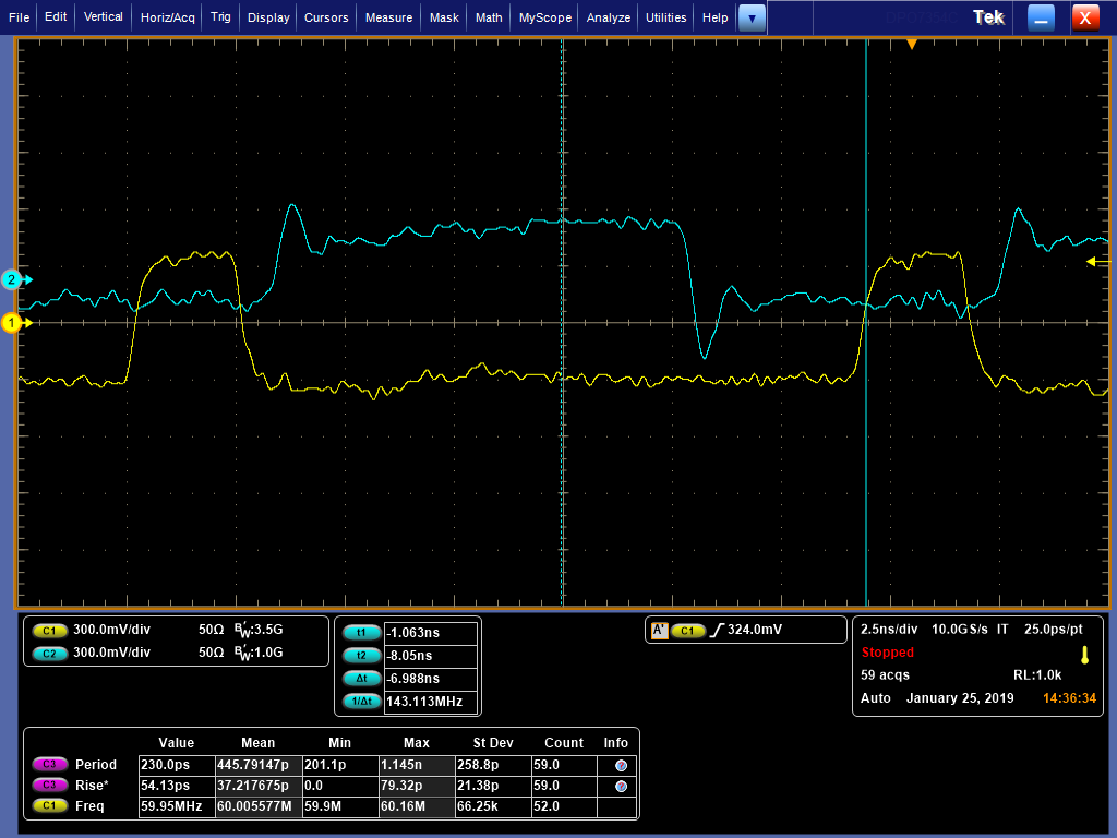
Another thing, we also found that there is some delay between two LVDS output CLK, about 925ps, is this acceptable?

  • Hi yf,

    Do you see this behavior on multiple systems? Also can you share an image of what the display looks like?

    Regards,
    I.K.
  • As this is the first product we use this solution, we only see this issue on 3 prototype boards, (more need to check). The defective display from LVDS driving and correct display from HDMI driving are as below.

    2. Can you help to confirm the LVDS data format in the datasheet, those G10, R15, R14 ... are referring to odd pixel green bit 0, odde pixel red bit 5...  Or is it referring to the DSC90387 pin number? 

  • Hi yf,

    They are referring to the pin number. You can map the pins to whatever color you want, but the pins will always be serialized on the LVDS lanes as shown in that figure.

    In your experiment, have you also tried setting only the R12 pin high and everything else to 0 to see what happens?

    Please also share your schematic and LCD datasheet. You can email them to i-anyiam@ti.com if you don't want to share it here.

    Regards,
    I.K.
  • hi I.K.

    It turns out our RGB mapping into DS90C387 does not match LCD format which is VESA, after modfied the input , the display became correct, thanks for your support.

    By the way, do you know what's the difference between DS90C387 and DS90C387A, which one is recommended for new design?

  • Hi yf,

    I'm glad you were able to fix the problem and thank you for reporting what the root cause was.

    The difference between the DS90C387 and DS90C387A is that the DS90C387 has DC balance data transmission and cable deskew features that the DS90C387A does not have. Since the 387A does not have these features it reduces the overall power dissipation, but cannot drive long cables like 387 can. You can make your decision between these two parts by weighing these trade-offs.

    Regards,
    I.K.