This thread has been locked.

If you have a related question, please click the "Ask a related question" button in the top right corner. The newly created question will be automatically linked to this question.

TCAN1042HGV-Q1: SAE J2962-2 per ISO 10605 and IEC 61000-4-2

Part Number: TCAN1042HGV-Q1
Other Parts Discussed in Thread: STRIKE

Dear all

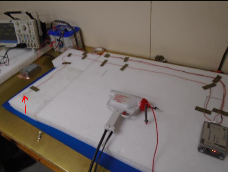
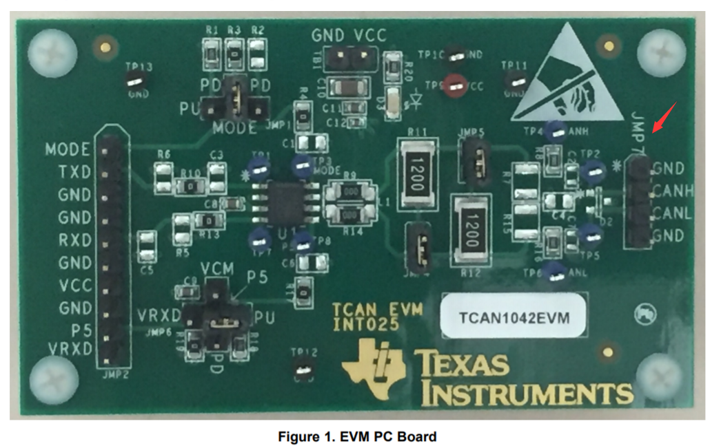
      I had test the CANH/CANL pin of TCAN1042HGV-Q1 device with System Level Electro-Static Discharge (ESD), but the device had been damaged. 

      I want to check SAE J2962-2 per ISO 10605  and IEC 61000-4-2 of datasheet are same to my test equipment.

      Please give me the SAE J2962-2 per ISO 10605  and IEC 61000-4-2 source file, thanks a lot.

  • Hi Went,

    We cannot share the full standards specifications (you need to get them from the standards bodies), but I can tell you that the J2962-2 testing used an ESD simulator with R = 2000 Ohms / C = 330 pF and the IEC 61000-4-2 testing used R = 330 Ohms / C = 150 pF. The J2962-2 tests were conducted with the devices installed in two test ECUs communicating with one another, each in a conductive housing but with only one tied to the upper ground plane of the ESD test table (per the required set-up in the standard). The IEC 61000-4-2 tests were performed on an EVM for the device that was placed on an insulating support on top of an IEC-standard test table (with upper grounding plane weakly biased to earth ground and lower grounding plane tied to both earth and the ESD simulator's return line).

    If you have any other questions please let us know.

    Regards,
    Max
  • Dear Max

         Thanks your reply. My test equipment is set R = 2000 Ohms / C = 330 pF,matched with your J2962-2 testing.

         But I don't understand J2962-2 tests, below picture is my test method, could you tell me unreasonable points ? Thanks 


  • Went,

    This looks similar, although there are some further set-up details defined in the standard. Here is a summary:

    - Table top is grounded, battery is placed on top with (-) terminal connected to both table top and DUTs. ESD simulator's ground connects to the table top as well.

    - A "monitoring DUT" is connected that may be similar in design to the "primary DUT" but is configured to have CAN bus termination: 120 Ohm || (60 Ohm + 60 Ohm, capacitor to ground placed at center point for filtering). This monitoring DUT is placed on the table-top ground plane and then connects to the primary DUT via a 1.7-m harness (which carries both CANH/CANL signals as well as battery/ground connections).

    - The primary DUT is placed on an insulating support so that it does not contact the table top. An additional 1.7-m cable connects the CANH/CANL lines from the primary DUT to ESD discharge points (un-insulated end points of the wiring harness). It is here that the ESD simulator strikes. The discharge path should be separated from the main harness between DUTs by 5 cm.

    If you would like, I can email you a test report for our device conducted by a third-party lab that has some photographs of the J2962-2 ESD set-up.

    Regards,
    Max
  • Dear  Max

          Yes, I want, please email to me. Thanks a lot.

          went.cao@wpi-group.com

  • Dear Max

    You said "but is configured to have CAN bus termination: 120 Ohm || (60 Ohm + 60 Ohm, capacitor to ground placed at center point for filtering).", could you draw a diagram to me? So that I cann't misunderstand. thanks a lot.
  • Hi Went,

    Sorry to be a little vague. If you look at Figure 17 in the TCAN1042HGV-Q1 datasheet you can see a diagram showing two different termination techniques: "standard termination" and "split termination." For the monitoring DUT in these tests, one standard termination is placed in parallel with one split termination. Let me know if that doesn't make sense.

    I will send you the test report now.

    Regards,
    Max
  • Dear Max

    I have two questions:

    1. In tests, why one standard termination is placed in parallel with one split termination ? Does it be only one way to test ?

    2. Other tests, like two standard terminations,or two split terminations, can it also pass the ESD standard ?

  • Hi Went,

    I don't know for sure why the standard was written in that way originally, but my guess is that it is because termination (via an effective resistance of ~60 Ohms) is required to be able to check for proper CAN functionality and placing the termination at the directly at the DUT (rather than the monitor) usually results in less stress to the DUT (since some of the transient energy may be shared with the complementary signal in the differential pair).

    Generally I wouldn't expect the different termination techniques to give major differences in ESD performance, although use of split termination may be beneficial in providing an additional low-impedance path to ground (via the 60-Ohm termination resistance) for higher-frequency transients.

    Max
  • Dear Max

    I had check the ESD report, on page 48, it doesn't show clearly where does the electrostatic gun hit ? Could you show to me ? Thanks a lot.

  • Hi Went,

    I've marked the strike location in this image:

    Regards,
    Max

  • Dear Max

    I probably know that how to test at that time. But in the datasheet of TCAN1042HGV-Q1 device,on page 5, it said ESD of CANH/CANL pins could be up to 8KV by IEC 61000-4-2, but it's not test directly on the CANH/CANL pins. I think the datasheet is not rigorous.

    Could you test ESD of CANH/CANL pins as my below test method,make sure that CANH/CANL pins could pass ESD 8KV by your test conditions ?

    My test method:

    Only one device, CAN bus line is 30mm, and the electrostatic gun hit to the line of CANH/CANL.

  • Hi Went,

    There were actual several different ESD tests performed on this device. What I've been describing so far has been the SAE J2962-2 testing. Separately, IEC 61000-4-2 ESD was evaluated as well. This set-up followed the IEC 61000-4-2 standard set-up and was performed on the device EVM. The contact point for the ESD gun was on the PCB within 1-2 cm of the DUT IC. These results are documented in the datasheet and labelled as IEC 61000-4-2. Let me know if this doesn't make sense.

    Max
  • Dear Max

    Look next message, Thanks.

  • Dear Max

    1. Sorry, I had said wrong, it's not IEC 61000-4-2, it is SAE J2962-2.

    Could the device EVM pass the SAE J2962-2 ESD ? I want to test the EVM as below:

    http://www.ti.com/tool/TCAN1042DEVM

    2.As you said, the device EVM could pass the IEC 61000-4-2 ESD, I have a question ,on the PCB within 1-2 cm of the DUT IC, is it the CANH/CANL pins ofJMP7 socket?

  • Went,

    I don't believe we've tested this device's EVM for SAE J2962-2 ESD since that set-up is defined to have discharges through a cable rather than directly to the DUT PCB. Based on the testing we have done, though, my assumption is that this test would pass up to at least 8 kV.

    For the IEC strike point - it is actually a little difficult to reliably connect the conical tip of the ESD generator to JMP7, and so instead the contact points were the upper pad of R7 and the lower pad of R12.

    Max