This thread has been locked.

If you have a related question, please click the "Ask a related question" button in the top right corner. The newly created question will be automatically linked to this question.

DS90UB933-Q1: How to talk to 933 with 954 chipset

Part Number: DS90UB933-Q1
Other Parts Discussed in Thread: ALP, USB2ANY, TIDA-01002

Hi,

we have a 954 de-serialiser  taking in 2 off 933 chips over 1meter STP link

Trying via alp v1.57 to talk to the chips.

I have so far got this via alp

I tried to run the following code as a script file but it fails at the first line. , just to see if is can connect

Am I missing the python libraries ?

# 954 ID 60 8'b (the default add. in TI's 954EVM board)
devAddr = 0x60
# "FPD3_PORT_SEL RX0"
board.WriteI2C (devAddr, 0x4c, 0x01) # RX_PORT 0 read / write
# "enable pass through"
board.WriteI2C (devAddr, 0x58, 0x58) # enable pass through
board.WriteI2C (devAddr, 0x5c, 0x18) # "SER_ALIAS_ID"
board.WriteI2C (devAddr, 0x5d, 0x60) # "SlaveID [0]"
board.WriteI2C (devAddr, 0x65, 0x60) # "SlaveAlias ​​[0]"

Any help appreciated.

  • Hello,
    Are you connected to UB954 and running it from Scripting Tab? Please post a picture of the whole ALP screen showing the profile you are connected to also. In partner information, not sure why port # is showing as N/A. Please show a screen shot of the exact error you are getting when you run the script.
    Thanks,
    Vishy
  • here is the full ALP screen.

    I manually put the

    I manually set the input mode from csi to RAW as it is strapped by the mode pin for csi at the minute as we are also designing with dual 953 board into a 954.

  • Hello,

    I notice in the screen shot enclosed you are running the script from System scripting tab. Instead you should use the "Scripting" tab. Please see below

    Thanks,

    Vishy

  • Figured that out , still no i2c on remote end, thinks a 913 is connected not a 933.

    Is there a simple script that can validate the 933 link with the 954?

  • DS90UB933 is same device as 913A and is qualified for up to 100MHz operation (versus 75MHz in 913A) with 12-bit payload. Registers are identical and hence ALP recognizes it as 913A.

    Thanks,
    Vishy
  • I see you are using 913 not 913A. So wanted to clarify above answer applies to 913 also. Thanks.
  • Hi , the part code on the actual device is UB933Q : Still not seeing any remote registers .

  • Hello,

    Please explain your 954/933 setup a little more. Are you using 954/933 EVMs or your own board? How are they powered? Are you using POC? If EVMs please review the 954 EVM user guide and note the following

    Thanks,

    Vishy

  • We are using STP and the 954 EVM with PDB pulled low so we can talk to the 954 on our receiver board.

    The link is 100n coupled on both sides of the cable. 

    Cable length on the bench is 1 metre.

  • Hello,

    Since PDB is pulled low on the 954 EVM you are not using 954. Are the I2C lines of the EVM connected to your receiver board (so you are using EVM as USB2ANY)?

    For successful 933 communication, in addition to setting up PORT_CONFIG (0x6D) Register STP mode and FPD3_MODE, you also have to setup the BCC_CONFIG register (0x58) bits 2:0 (BC_FREQ_SELECT) to 2.5Mbps. Please review 954 Data Sheet.

    Thanks,
    Vishy
  • Yes , using the 954 evm as usb2any . want to know the registers to setup. The previous screen grab showed the 2.5Mbps link as being present. SO d oI have to program the registers mentioned to get the I2C comms running
  • a) Please see enclosed screen capture. I have shown a sample 954/953 remote registers tab. In the remote registers window, you have to choose the RX port for communication to establish. Did you select it and try?

    b) In the 954 registers tab, make sure you have selected properly register 0x4C bits. In this register only you choose which port registers you are going to access and their r/w access.

    c) Also, check registers 0x5B and 0x5C are initialized with the serializer id and alias for the port you are communicating with.

    d) Also, on the scripting tab, you can check  using the "board.ReadI2C(devAddrs,  0x0)" whether you are able to read the serializer address correctly in register 0x0. Here devAddrs is the serializer address. See window below

  • I can now see the 2 x  933 chips  : one chip is i2c at 0xB4 and has an image sensor attached with i2c address 0x90 , the other chip is i2c at 0xBA and image sensor at i2c 0xBA.

    I ran the following script , but can only see the RX0 remote registers once this is run , [ assigning alias to 933 of 0x18 and 0x19] : any idea why only seeing one set of registers

    # 954 ID 60 8'b (the default add. in TI's 954EVM board)
    # devAddr = 0x60 : first channel in 4 port pcb uses this address
     # "FPD3_PORT_SEL RX0"
     
    import time
    board.WriteI2C(0x60, 0x4c, 0x01) # RX_PORT 0 read / write to ser1 chip
    # 4C holds the key
     # "enable pass through"
    board.WriteI2C(0x60, 0x58, 0x58) # enable pass through : back channel enable and crc enable : first serialiser is i2c address B4 in register 0x58
    board.WriteI2C(0x60, 0x5c, 0x18) # "SER_ALIAS_ID" : alias address
    board.WriteI2C(0x60, 0x5d, 0x90) # "SlaveID [0]"  : id of Aptina sensor #1 : set by resistor
    board.WriteI2C(0x60, 0x65, 0x60) # "SlaveAlias ​​[0]"
    board.WriteI2C(0x60, 0x4c, 0x10) # RX_PORT 1 read / write to ser2 chip
    # 4C holds the key
     # "enable pass through"
    board.WriteI2C(0x60, 0x4c, 0x10) # RX_PORT 0 read / write to ser1 chip
    board.WriteI2C(0x60, 0x58, 0x58) # enable pass through : back channel enable and crc enable : first serialiser is i2c address BA in register 0x58
    board.WriteI2C(0x60, 0x5c, 0x19) # "SER_ALIAS_ID" : alias address
    board.WriteI2C(0x60, 0x5d, 0xba) # "SlaveID [0]"  : id of Aptina sensor #1 : set by resistor
    board.WriteI2C(0x60, 0x65, 0x60) # "SlaveAlias ​​[0]"

  • Hello,

    In your script, 0x4C register is not initialized correctly for Port 1. It should be set 0x12 not 0x10. Then only writes are enabled. Also, make sure register 0x0C is initialized properly: By default both ports are enabled in this register.

    Thanks,
    Vishy
  • Thanks Vishy : I ran the following script and can see both remote register sets at 0x18 and 0x19 : Just need to see if I can read from the image sensor now

    board.WriteI2C(0x60, 0x4c, 0x01) # RX_PORT 0 read / write to ser1 chip

    # 4C holds the key
     # "enable pass through"
    board.WriteI2C(0x60, 0x58, 0x58) # enable pass through : back channel enable and crc enable : first serialiser is i2c address B4 in register 0x58
    board.WriteI2C(0x60, 0x5c, 0x18) # "SER_ALIAS_ID" : alias address
    board.WriteI2C(0x60, 0x5d, 0x90) # "SlaveID [0]"  : id of Aptina sensor #1 : set by resistor
    board.WriteI2C(0x60, 0x65, 0x60) # "SlaveAlias ​​[0]"


    # 4C holds the key
     # "enable pass through"
    board.WriteI2C(0x60, 0x4c, 0x12) # RX_PORT 1 read / write to ser2 chip
    board.WriteI2C(0x60, 0x58, 0x58) # enable pass through : back channel enable and crc enable : first serialiser is i2c address BA in register 0x58
    board.WriteI2C(0x60, 0x5c, 0x19) # "SER_ALIAS_ID" : alias address
    board.WriteI2C(0x60, 0x5d, 0xba) # "SlaveID [1]"  : id of Aptina sensor #2 : set by resistor
    board.WriteI2C(0x60, 0x65, 0x60) # "SlaveAlias ​​[1]"

    # set RX port control register

    board.WriteI2C(0x60, 0x0c, 0xb3) # enable rx on both ports and all ports pass

    ##################################################################

    Note : The sensors we use are the AS0140AT as used in TIDA-01002 reference design.

    Are  there any scripts available to support the bring up of this sensor , to color bar test mode or video output.

    regards

  • Hello,

    I suggest you keep SlaveAlias[0] and SlaveAlias[1] id different from deserializer id 0x60 to avoid confusion.
    Regarding AS0140AT sensor initialization, I suggest you check with ON Semi. They would be able to ensure you have the correct driver version. Also, I notice the following document (probably you are already aware) has a nice summary of SERDES initialization required
    www.ti.com/.../tiduc90c.pdf

    Thanks,
    Vishy

  • Hi Vishy,
    does board.writeI2C and boardReadI2C support 16 bit register address and 16 bit data ?
    IF not, what is the method to achieve this ?
  • Hello,

    Yes, 16-bit read/write are supported.  

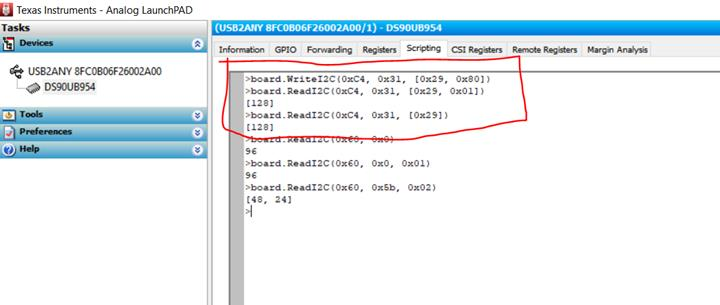
    I have shown below 16-bit read/write examples of imager (i2c address 0xC4).

    a) First register address 0x3129 is written with a value of 0x80 using the command

        board.WriteI2C(0xC4, 0x31, [0x29, 0x80])

    b) Then register 0x3129 is read back using the command

        board.ReadI2C(0xC4, 0x31, [0x29, 0x01])

    c) Alternatively, you can also use the following command to read back  a single byte

        board.ReadI2C(0xC4, 0x31, [0x29])

    To use this feature, please make sure you have installed the latest ALP frame work utility (v1.57.0010) and ALP-PROFILE-UPDATE from the web

    http://www.ti.com/tool/ALP

    Thanks,

    Vishy

  • So , if it is a 16 bit register content then the 0x02 allows for the 2 byte read back from the register ?

    and If you want to write a 16 bit command then  , is it like   board.WriteI2C(0xC4, 0x31, [0x29, 0x8002]) to put 0x8002 into 0x3129 

    A lot of the ONsemi imagers use the 16 bit register model..

  • Addressing 2 sensors with the attached code , I was able to read the contents of register ox0000 on an as0140at sensor which should hold 0x0062. this worked for port 0 on the 954 but not port 1 . It is as if i2c is not enabled correctly on port 1 ?  Do I need to set ox4c register to 0x12 before any I2C port 1 operations 

    ############################################################

    # 954 ID 60 8'b (the default add. in TI's 954EVM board)
    # devAddr = 0x60
    # "FPD3_PORT_SEL RX0"

    import time
    #reset and initialize AS0140AT

    # Set up IDs
    UB954 = 0x60
    UB933ID = 0x30
    UB933A = 0x18
    UB933B = 0x19
    AS0140IDA = 0x90
    AS0140A = 0xC1
    AS0140IDB = 0xBA
    AS0140B = 0xC2
    ############################################################################
    # Set up Port0
    board.WriteI2C (UB954, 0x4c, 0x01) # RX_PORT 0 read / write
    print "enable pass through"
    board.WriteI2C (UB954, 0x58, 0x58) # enable pass through
    # Set up SER Alias ID
    board.WriteI2C (UB954, 0x5c, UB933A) # "SER_ALIAS_ID"
    # Set up Slave/Camera ID
    board.WriteI2C (UB954, 0x5d, AS0140IDA) # "SlaveID [0]"
    # Set up Slave/Camera Alias ID
    board.WriteI2C (UB954, 0x65, AS0140A) # "SlaveAlias ​​[0]"

    ##############################################################
    # Set up Port1
    board.WriteI2C (UB954, 0x4c, 0x12) # RX_PORT 1 read / write
    # "enable pass through"
    board.WriteI2C (UB954, 0x58, 0x58) # enable pass through
    # Set up SER Alias ID
    board.WriteI2C (UB954, 0x5c, UB933B) # "SER_ALIAS_ID"
    # Set up Slave/Camera ID
    board.WriteI2C (UB954, 0x5d, AS0140IDB) # "SlaveID [1]"
    # Set up Slave/Camera Alias ID
    board.WriteI2C (UB954, 0x65, AS0140B) # "SlaveAlias ​​[1]"

    # enable 12 bit HF mode on serialiser ports 0/1 and stp
    board.WriteI2C (UB954, 0x4c, 0x01) # RX_PORT 0 read / write
    board.WriteI2C(UB954,0x6D,0x7A) # 12 bit HF mode and STP port 0
    board.WriteI2C (UB954, 0x4c, 0x12) # RX_PORT 1 read / write
    board.WriteI2C(UB954,0x6D,0x7A) # 12 bit HF mode and STP port 1
    board.WriteI2C(UB954,0x0C,0xB3) # both RX ports PASS and Active
    print "PORT 0/1 SETUP DONE"
    #############################################################################
    # setup 400MHz CSI clock
    #############################################################################
    # Enable 400Mbps CSI in UB954
    #

    # Set CSI_TX_SPEED to select 400Mbps
    board.WriteI2C(UB954, 0x1F, 0x3)

    # Set PLL Clock divider to 32
    #board.Ind_Acc_Write(7, 0xA, 0x80)
    board.WriteI2C(UB954, 0xB0, (0x7 << 2))
    board.WriteI2C(UB954, 0xB1, 0xA)
    board.WriteI2C(UB954, 0xB2, 0x80)

    # Set PLL CP current
    #board.Ind_Acc_Write(0x7, 0x7, 0xE2)
    board.WriteI2C(UB954, 0xB0, (0x7 << 2))
    board.WriteI2C(UB954, 0xB1, 0x7)
    board.WriteI2C(UB954, 0xB2, 0xE2)

    # Set CSI Timing parameters
    #board.Ind_Acc_Write(0x0, 0x40, [0x83, 0x8D, 0x87, 0x87, 0x83, 0x86, 0x84, 0x86, 0x84]])
    board.WriteI2C(UB954, 0xB0, 0x2) # set auto-increment, page 0
    board.WriteI2C(UB954, 0xB1, 0x40) # CSI Port 0
    board.WriteI2C(UB954, 0xB2, 0x83) # TCK Prep
    board.WriteI2C(UB954, 0xB2, 0x8D) # TCK Zero
    board.WriteI2C(UB954, 0xB2, 0x87) # TCK Trail
    board.WriteI2C(UB954, 0xB2, 0x87) # TCK Post
    board.WriteI2C(UB954, 0xB2, 0x83) # THS Prep
    board.WriteI2C(UB954, 0xB2, 0x86) # THS Zero
    board.WriteI2C(UB954, 0xB2, 0x84) # THS Trail
    board.WriteI2C(UB954, 0xB2, 0x86) # THS Exit
    board.WriteI2C(UB954, 0xB2, 0x84) # TLPX

    # Set CSI Timing parameters
    #board.Ind_Acc_Write(0x0, 0x60, [0x83, 0x8D, 0x87, 0x87, 0x83, 0x86, 0x84, 0x86, 0x84]])
    board.WriteI2C(UB954, 0xB0, 0x2) # set auto-increment, page 0
    board.WriteI2C(UB954, 0xB1, 0x60) # CSI Port 1
    board.WriteI2C(UB954, 0xB2, 0x83) # TCK Prep
    board.WriteI2C(UB954, 0xB2, 0x8D) # TCK Zero
    board.WriteI2C(UB954, 0xB2, 0x87) # TCK Trail
    board.WriteI2C(UB954, 0xB2, 0x87) # TCK Post
    board.WriteI2C(UB954, 0xB2, 0x83) # THS Prep
    board.WriteI2C(UB954, 0xB2, 0x86) # THS Zero
    board.WriteI2C(UB954, 0xB2, 0x84) # THS Trail
    board.WriteI2C(UB954, 0xB2, 0x86) # THS Exit
    board.WriteI2C(UB954, 0xB2, 0x84) # TLPX

    #############################################################################
    # setup GPO0 REMOTE TO CONTROL as0140at RESET PULSE port 0 only
    # GPIO 0 IS RESET : check 933 registers OK
    # writes are interpreted as (sensor alias , reg msb , [reg lsb , data]

    #############################################################################
    board.WriteI2C(UB933A,0x0D,0x01) # set gpio 0 to output 0x05
    board.WriteI2C(UB933A,0x0D,0x09) # set pin 0 high
    time.sleep(0.1) # 100mSeCond delay
    board.WriteI2C(UB933A,0x0D,0x01) # bring gpio0 low to reset sensor
    time.sleep(1)
    board.WriteI2C(UB933A,0x0D,0x09) # GPIO 0 HIGH AGAIN
    print " Sensor A reset pulse sent"
    board.WriteI2C(UB933B,0x0D,0x01) # set gpio 0 to output 0x05
    board.WriteI2C(UB933B,0x0D,0x09) # set pin 0 high
    time.sleep(0.1) # 100mSeCond delay
    board.WriteI2C(UB933B,0x0D,0x01) # bring gpio0 low to reset sensor
    time.sleep(1)
    board.WriteI2C(UB933B,0x0D,0x09) # GPIO 0 HIGH AGAIN
    print " Sensor B reset pulse sent"
    ############################################################################
    # try to set sensors up for color bar : try and read a register first :
    ############################################################################
    # ALP can do i2c 16 bit register operations :
    # read back
    print (" chip version a",board.ReadI2C(AS0140A,0x00, [0x00,1]))

    print ("chip version a ",board.ReadI2C(AS0140A,0x00, [0x00,2]))

    print (" chip version b",board.ReadI2C(AS0140B,0x00, [0x00,1]))

    print ("chip version b ",board.ReadI2C(AS0140B,0x00, [0x00,2]))

    board.WriteI2C(AS0140B,0x00, [0x40,0x8e00]) # get current system state
    time.sleep(0.1)
    board.WriteI2C(AS0140B,0x00, [0x40,0x8e01]) # initialise sensor
    time.sleep(0.1)
    board.WriteI2C(AS0140B,0xc8, [0x8c,0x02]) # camera mode select
    board.WriteI2C(AS0140B,0xc8, [0x8f,0x02]) # test pattern select
    board.WriteI2C(AS0140B,0x00, [0x40,0x8100])

    #board.WriteI2C(AS0140A,0x31, [0x32,0x24])
    # read back

    board.WriteI2C(AS0140A,0x00, [0x40,0x8e00])
    time.sleep(0.1)
    board.WriteI2C(AS0140A,0x00, [0x40,0x8e01]) # initialise sensor
    time.sleep(0.1)
    board.WriteI2C(AS0140A,0xc8, [0x8c,0x02]) # camera mode select
    board.WriteI2C(AS0140A,0xc8, [0x8f,0x02]) # test pattern select
    board.WriteI2C(AS0140A,0x00, [0x40,0x8100]) # set state

    #############################################################################
    # setup CSI port for one port First
    #############################################################################
    board.WriteI2C (UB954, 0x4c, 0x01) # RX_PORT 0 read / write
    board.WriteI2C(UB954,0x7C,0x00) #PORT SELECT : FV-high and LV-high RAW10 mode

    board.WriteI2C(UB954,0x6E,0x99) #BC GPIO

    board.WriteI2C(UB954,0x70,0x1F) #RAW ID

    board.WriteI2C(UB954,0x71,0x1F) #RAW ID

    board.WriteI2C(UB954,0x7C,0xC0) #RAW 10 8BIT

    board.WriteI2C(UB954,0x32,0x01) #CSI TX PORT1

    board.WriteI2C(UB954,0x33,0x03) #CSI OUT ENABLE

    board.WriteI2C(UB954,0x20,0x00) #CSI FORWARDING

    board.WriteI2C(UB954,0x1F,0x03) # CSI 400MHz
    ##############################################################################

  • >>>>If you want to write a 16 bit command then , is it like board.WriteI2C(0xC4, 0x31, [0x29, 0x8002]) to put 0x8002 into 0x3129

    It should be
    board.WriteI2C(0xC4, 0x31, [0x29, 0x80, 0x02])

    Basically a python list (in square brackets) of all the address and data bytes to be written in order

    >>>if it is a 16 bit register content then the 0x02 allows for the 2 byte read back from the register ?

    To read back multiple data bytes (say 2) use
    board.ReadI2C(0xC4, 0x31, [0x29, 0x02])

    Read call returns a list of bytes read

    Thanks,
    Vishy
  • >>>>Addressing 2 sensors with the attached code , I was able to read the contents of register ox0000 on an as0140at sensor which should hold 0x0062. this worked for port 0 on the 954 but not port 1 . It is as if i2c is not enabled correctly on port 1 ?  Do I need to set ox4c register to 0x12 before any I2C port 1 operations

    Yes. You need to set 0x4C register to 0x12 before any I2C port 1 operation. Please refer data sheet picture below.

    thanks,

    Vishy

  • Also in the attached code, writing the reset pulse to 933A also writes it to 933B at the same time so I am getting a double pulse . I was trying to reset individually. Is the alias setup incorrect or is it some global broadcast bit that is set incorrectly ?

  • >>>Is the alias setup incorrect or is it some global broadcast bit that is set incorrectly ?

    I think your alias setup (933A = 0x18, 933B = 0x19) might be the issue. Please refer table 102 of the DS. If you initialize Port 1 register 0x5C to 0x19, the 7-bit SER_ALIAS_ID is 0x18 which is the same as 933A in addition to turning on SER_AUTO_ACK. Suggest you change 933B to say 0x30.

    Thanks,
    Vishy
  • Thanks Vishy , that cleared the issue of double pulse. Also found out that 2nd 933 had i2c address of BA which is the same as the 2nd As0140at sensor. Changed it to B2 via resistor change and I can now read reg 0000 [0x0062] in both sensors.

  • That's great to know. Thanks. I will make the thread status closed.