This thread has been locked.

If you have a related question, please click the "Ask a related question" button in the top right corner. The newly created question will be automatically linked to this question.

DS90UB954-Q1: How to check the margin by manual operation

Part Number: DS90UB954-Q1

Hi team,

I experimentally done the manual margin analysis using EVM.

I refer to the document of the link below.

http://www.ti.com/lit/an/snla301/snla301.pdf

http://www.ti.com/lit/ug/snlu243/snlu243.pdf

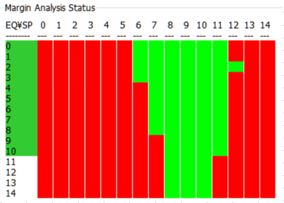
First, I got the results using the margin analysis of the GUI and confirmed whether the same result can be obtained by manual setting.

The results obtained by GUI margin are as follows.

Therefore, there is a doubt about the error check register and its procedure.

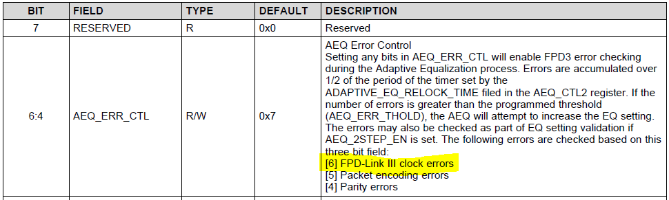
In the document, registers whose errors should be confirmed are described as 0x4D[5:2] and 0x4E[5].

However, as a result of manual verification, when checking 0x4D [5: 2] and 0x4E [5], these registers remain 0 if SP is small or large.

The results at that time are as follows.

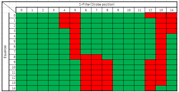
When SP is close to 0 or close to 14, register 0x4D is 0x00 and 0x4E is 0x02 in many cases.

That is, both PASS and LOCK are 0, and communication is not established.

Empirically, if it is UNLOCK status, 0x4E [2]: CABLE FAULT seems to be detected.

Also, I think that this register corresponds to the following FPD-LINK III clock, should this register also be checked?

Or will it be necessary to change the SP from the condition of stable locking?

We would like to establish a valid manual verification method.

Best regards,

Tomoaki Yoshida

  • Hello Yoshida-san,

    Can you please share the script you are using for this?

    I would also suggest looking at ub954_margin_analysis.py  under C:\Program Files (x86)\Texas Instruments\Analog LaunchPAD v1.57.0010\PreDefScripts\DS90UB954\ub954_margin_analysis_script. 

    FPD-Link III clock errors are included by checking for FPD encoder errors. The register you mentioned is used to control which errors are monitored during AEQ (it is not an error status register).

    Regards,

    Zoe

  • Hi Zoe-san,

    Thank you for your support.
    I am not using a script.
    I changed Register 0xB2 in GUI, then I read 0x4D and 0x4E data.

    I confirmed the ub954_margin_analysis_script file.
    I understand that it is defined as Lock when 0x4D [5: 2] and 0x4E [2] are 0 and 0x4D [0] is 1.
    And when it succeeds 10 times in 10 trials, it displays Green.

    Is this correct?

    I will do margin analysis manually according to this procedure if my recognition is correct.

    Best regards,
    Tomoaki Yoshida
  • Hello Yoshida-san,

    Yes, you are correct about how the status is monitored.

    You should also set the parity error threshold to 1 and enable the encoder CRC:

    # set Parity Error Threshold Hi Register
    board.WriteI2C(devAddr_DES, 0x05, 0x00)
    time.sleep(0.1)
    # set Parity Error Threshold Lo Register
    board.WriteI2C(devAddr_DES, 0x06, 0x01)
    time.sleep(0.1)
    # Enable Encoder CRC error capability
    enc_crc = s.board.ReadReg(0x4A, 0x01)
    s.board.WriteReg(0x4A, (enc_crc | 0x10))

    Regards,

    Zoe