This thread has been locked.

If you have a related question, please click the "Ask a related question" button in the top right corner. The newly created question will be automatically linked to this question.

TL16C752D: I am trying to use the RX/TX FIFOs by reading the LSR.

Part Number: TL16C752D

Hi,

I am trying to use the TL16C752D  RX/TX FIFOs using polling. I'm only reading the LSR for the status of THR/RHR. The RX portion works with no problems. It's in the TX mode where I watch for LSR THR Empty. Currently, I have the FIFOs Levels set at 0 and it seems to work for awhile then seems to get stuck when the TX FIFO is full.

Should I be polling something other than the LSR?

Maybe I should set up interrupts (we don't have interrupts connected) and poll the IIR instead?

I have the UART set up to run at 115200 Baud and am streaming a 292 Byte Packet between this UART and a UART on a separate processor board(RABBIT). It will run fine for awhile but then I start getting timeouts

from the RABBIT.

Any thoughts from the community on this?

Thanks you for the help,

Reif Heck

  • Hello Reif,

    When the TX FIFO is full, some characters written into the THR will be lost - would this result in an time-out in your application?

    If you give some time for the FIFO to transmit all of its data, does it eventually become empty? And if so, does normal operation seem to resume? (If not, what do you need to do to clear the issue and resolve the time-out?)

    As you suggested, enabling interrupts and polling IIR may provide some useful data when trying to understand the nature of the issue.

    Regards,
    Max
  • Hey Reif,


    "Should I be polling something other than the LSR?"
    You shouldn't need to as LSR bit 0 should tell you when data is ready to read and bit 5 tells you when THR is empty.

    An alternative approach you could try is setting the TX/RX trigger level in FCR and then polling the FIFORdy register.

    "Maybe I should set up interrupts (we don't have interrupts connected) and poll the IIR instead?"
    If you set up the INT then you could actually just check logic level of the INT pin of the device instead of polling the IIR unless you are all out of GPIs.

    Thanks,
    -Bobby
  • Hi Max,

    Thank you for your reply.

    I forgot to mention that I am using XON1(0x7E)/XOFF1(0x7F) as my beginning and ending packet delimiters for my receive side. If I enable the Rx FIFO with trigger level set to 0, I'm able to receive packets from the sending side all day long without issue. The maximum receive packet size is 20 bytes.

    The maximum/minimum TX packet sizes are 292/14 bytes. So I am setting the 485EN, 485LG, and RCVEN bits in the AFR register. I only use the 485LG bit when sending responses larger than 60 bytes.

    The streaming of packet sizes smaller than 60 bytes is no issue. It's the 292 byte packets that are eventually timing out.

    I may try enabling and polling the IIR.

    Thanks again,

    Reif

  • Thanks Bobby,

    I was just thinking of trying your alternative approach. I'll let you and Max know how it turns out.

    Thanks again for the help,
    Reif
  • Max,

    Are the TxReady/RxReady signals only for DMA according to the data sheet? I have those hooked to the processor GPIO pins. The timing diagrams show these signals during FIFO/NON FIFO Modes.

    Thanks!

    Reif

  • Hey Reif,

    You should be able to use the TXRDY'/RXRDY' lines for your application (based on your previous posts) to check if the TX/RX FIFO has reach its trigger points. Setting DMA=0 just makes it so the TXRDY/RXRDY trigger upon one byte (similar to just polling LSR like you previously were doing) while DMA=1 just makes the TXRDY/RXRDY pins trigger upon the trigger level you set in the FCR.

    Thanks,

    -Bobby

  • Thanks Bobby,

    The data sheet is a little confusing about this point. So in order to use this, DMA = 1 allows me to use TxReady/RxReady signals for the FIFO? I'll definitely give that a try.

    Thanks again,

    Reif

  • Hi Bobby,

    I've decided to try it without FIFOs or interrupts just to see how it works.

    The steps in my state machine are:

    • Rx Packet State: When nRxReady goes low, I read data until I see the ending delimiter (0x7F). I send this as well and go to Verify Packet State
    • Verify Packet State: I verify the received packet and get the response packet. I then go to  Tx Packet State.
    • Tx Packet State: When nTxReady goes low, I transmit the data until I see the the ending delimiter (0x7F). I send this as well. I then return to RX Packet State

    My questions are:

    • Can I use nTxReady/nRxReady if I don't have interrupts or FIFIOs enabled. I don't see any other way to tell if I can Receive/Send?
    • Do I have to control DTR manually for our Transceiver?
    • Do RCVEN and 485EN need need to be enabled to do this?

    Thanks Bobby,

    Reif

  • Hi Max,

    I've decided to try it without FIFOs or interrupts just to see how it works.

    The steps in my state machine are:

    • Rx Packet State: When nRxReady goes low, I read data until I see the ending delimiter (0x7F). I send this as well and go to Verify Packet State
    • Verify Packet State: I verify the received packet and get the response packet. I then go to  Tx Packet State.
    • Tx Packet State: When nTxReady goes low, I transmit the data until I see the the ending delimiter (0x7F). I send this as well. I then return to RX Packet State

    My questions are:

    • Can I use nTxReady/nRxReady if I don't have interrupts or FIFIOs enabled. I don't see any other way to tell if I can Receive/Send?
    • Do I have to control DTR manually for our Transceiver?
    • Do RCVEN and 485EN need need to be enabled to do this?

    Thanks Max,

    Reif

  • Hey Reif,

    "Can I use nTxReady/nRxReady if I don't have interrupts or FIFIOs enabled. I don't see any other way to tell if I can Receive/Send?"
    Yes the TXRDY and RXRDY pins are outputs which work whether you set interrupts or the FIFO (essentially they will toggle regardless of if you want them to or not).

    From the steps you described, what you would need to do when transmitting is check if TXRDY is low: If low then you can send one byte of data. If TXRDY is high, it means you need to wait for the byte to finish transmitting. Repeat this until you send your ending delimter 0x7F. (failing to wait for TXRDY to go low means you may overwrite the data in THR from your earlier transaction)

    For RXRDY, you simply read everytime RXRDY is low.

    "Do I have to control DTR manually for our Transceiver?"
    Yes, you will need to perform a write on MCR bit0 to control the DTR line.

    "Do RCVEN and 485EN need need to be enabled to do this?"

    I assume when you mean 'this' it is in reference in controlling DTR. If so, then you do not need RCVEN or 485EN on inorder to control DTR manually.

    Thanks,
    -Bobby
  • Hi Bobby,

    Thanks for the reply!

    Sorry but I am having a hard time with the data sheet.

    I have been trying to get RX/TX to work without FIFOs or Interrupts. I thought I would go back to the basics as follows:

    The steps in my state machine are:

    • Rx Packet State: When nRxReady goes low, I read data until I see the ending delimiter (0x7F). I send this as well and go to Verify Packet State
    • Verify Packet State: I verify the received packet and get the response packet. I then go to  Tx Packet State.
    • Tx Packet State: When nTxReady goes low, I transmit the data until I see the the ending delimiter (0x7F). I send this as well. I then return to RX Packet State

    My questions are:

    • Can I use nTxReady/nRxReady if I don't have interrupts or FIFIOs enabled. I don't see any other way to tell if I can Receive/Send?
    • Do I need anything enable to use nTxReady/nRxReady (like RCVEN and 485EN)?
    • Do I have to control DTR manually for our Transceiver in this case? I know that DTR gets automatically controlled when 485EN is enabled.

    This is driving me crazy and I have combed trough the data sheet to understand. Maybe you can point to soemthing that might trigger an AHA!

    Thank you Bobby,

    Reif

  • Hey Reif,

    "Rx Packet State: When nRxReady goes low, I read data until I see the ending delimiter (0x7F). I send this as well and go to Verify Packet State
    Verify Packet State: I verify the received packet and get the response packet. I then go to Tx Packet State
    "
    I see no problems here.

    "Tx Packet State: When nTxReady goes low, I transmit the data until I see the the ending delimiter (0x7F). I send this as well. I then return to RX Packet State"
    You would need to check TXRDY every time you send one byte of data. Basically when TXRDY is low, you can send one byte of data because in your set up you are disabling the FIFO. After TXRDY goes low you can send your next byte of data (everytime you load a byte into THR the TXRDY will go high and you will need to wait for it to go low again).

    Your Tx Packet State looks good as long as you don't try to send all your data in one go (wait for TXRDY to go low before sending another byte) because you could accidentally overrun THR.

    "Can I use nTxReady/nRxReady if I don't have interrupts or FIFIOs enabled. I don't see any other way to tell if I can Receive/Send?"
    Yes.

    "Do I need anything enable to use nTxReady/nRxReady (like RCVEN and 485EN)?"
    No.

    "Do I have to control DTR manually for our Transceiver in this case? I know that DTR gets automatically controlled when 485EN is enabled."
    Yes, if the receiver is looking at the DTR line then you do. If DTR is something the receiver does not need to look at then you do not need to set DTR. (I mean DTR does not need to be set for you to send or receive data and is unrelated to TXRDY and RXRDY)

    Thanks,
    -Bobby
  • Thank you Bobby,

    The nDTR line is only controlling the TX(DE) side of the Transceiver. The RX(RE) side of the transceiver is grounded (always on).

    In my RxData/TxData  functions check for rxReady/txReady before receiving/transmitting a byte.

    For some reason it looks like I have a byte still sitting in the RHR after I transmit the response. Do I need to read the RHR to clear this or clear the RxFifo?

    Or do you suggest controlling both DE/RE of the transceiver with nDTR?

    Thank you,

    Reif

  • Hey Reif,

    "For some reason it looks like I have a byte still sitting in the RHR after I transmit the response."
    Do you have the loopback feature enabled by accident? (MCR bit 4)

    " Do I need to read the RHR to clear this or clear the RxFifo?"
    What data is stored there after you send a bit?

    "do you suggest controlling both DE/RE of the transceiver with nDTR?"
    This is just preference, I would try using TXRDY and RXRDY first and if you don't run into any bumps just go with this route, otherwise you will need to manually set the DTR which would take some extra time to do.

    Thanks,
    -Bobby
  • Hi Bobby,

    Loop back is not enabled. I check to be sure it is 0 during initialization. I have tested Loop back and it works like a champ.

    I just now put a check in the receive function to see if a byte is still there. I haven't tested it yet.

    The way this system works is:

    • There is a Sensor and a Controller talking over RS485
    • The Sensor only sits and waits for a command packet from the Controller
    • The Controller sends a command packet.
    • The Sensor receives the command packet and verifies it.
    • Once the Command Packet is verified, the sensor creates a response packet.
    • The response packet is sent to the Controller.
    • The Controller receives the response packet and checks if it is good. If so the Controller acts on the response.
    • The Controller sends another command packet to the Sensor.

    The issue i am seeing is that I never see the rxReady after the 1st byte unless I have 485EN and RCVEN set.

    The TI16C752D is initialized on startup as follows:

    EFR = 0x00

    IER = 0x00

    MCR = 0x00

    FCR = 0x00

    LCR = 0x03 (Normal operation)

    AFR = 0x14 (485EN and RCVEN = 1)

    Thanks again for the help Bobby,

    Reif

  • Hey Reif,

    Its been a while since I've used this device so I will have to try to see if I can get my set up up and running tomorrow to do some testing and provide some better support here.

    "The issue i am seeing is that I never see the rxReady after the 1st byte unless I have 485EN and RCVEN set."
    I could have sworn the RXRDY triggered after receiving the first byte. I'll experiment with this tomorrow.

    I'll copy your initialization set up and see if I get the same thing.

    Thanks,
    -Bobby
  • Thank you Bobby,

    I really appreciate it. You ca probably show what I have been doing wrong. ;~)

    Thanks again,

    Reif

  • Hey Reif,

    Wanted to give you an update here. One of my coworkers currently has my power supply, I'm working to get it back in the afternoon. I'm also stuck in meetings until 4:30pm today so I won't get to play around with this until 4:30ish. I'll do testing today and get back to you before I leave though.

    Thanks,
    -Bobby
  • Thanks you Bobby,

    I really appreciate it.

    Reif

  • Hey Reif,

    For some reason I am not able to get the TXRDY to even go high when sending a byte into THR. Been stuck trying to debug this for about an hour but no avail. I'm going to ask our design team to see what the requirements are inorder to get TXRDY and RXRDY to toggle.

    Thanks,
    -Bobby
  • Thank you Bobby!

    That is what has been driving me crazy for awhile. ;~)

    Thanks again,
    Reif
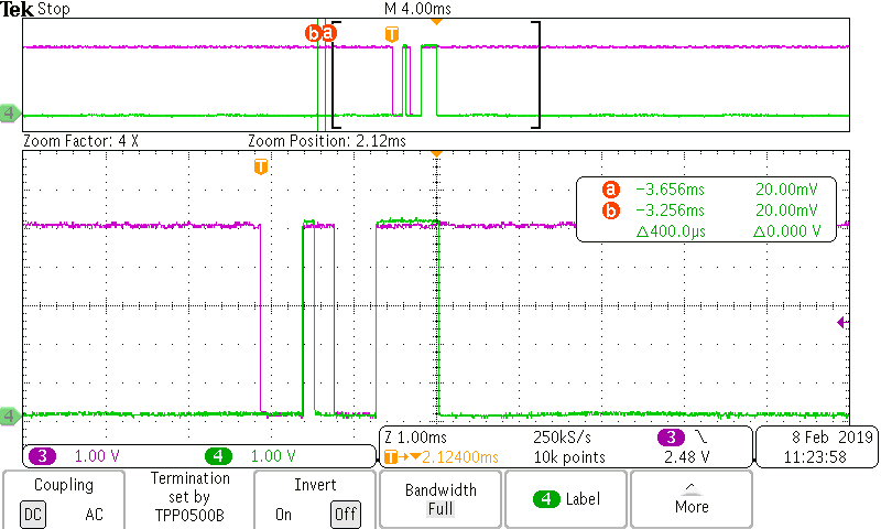
  • Hey Reif,

    I was finally able to get TXRDY to toggle....... So it looks like there is a requirement where you must perform a read of IER (I havent tried other registers yet) and then when you send data to THR TXRDY will toggle.

    My steps:

    After initializing the registers:

                       default_IER = 0x00,

                       default_FCR = 0x00,

                       default_MCR = 0x00,

                       default_LCR = 0x07;

                       default_AFR = 0x14;

    then I read register IER (its 0x00).

    After this I send 0xAA twice again:

    IOW is purple which I use to trigger the o-scope. I see that TXRDY toggles after this. Previously without doing a read of IER, TXRDY stays latched.

    Thanks,

    -Bobby

  • Hi Bobby,

    WOW! I would not have even guessed that! I kept scoping both the TXRDY/RXRDY lines (I have these connected to GPIO Pins on the processor as well to read them) and saw TXRDY Latched forever.

    That is a good find!

    So I'll initialize registers as follows:

    default_IER = 0x00,

    default_FCR = 0x00,

    default_MCR = 0x00,

    default_LCR = 0x07;

    default_AFR = 0x14;

    Read TXRDY

    If set, write a byte to THR

    Then read register IER = 0x00

    Then read TXRDY

    If set, write a byte to THR

    and so on until finished sending the last byte

    I'll give this a try and let you know how it works.

    Thank you Bobby,

    Reif

  • Hey Reif,

    You should probably perform the read of IER after initializing everything.

    After that I don't think you need to read it again.

    From there you should be able to perform your TXRDY check and send data.

    -Bobby
  • Thank you Bobby,

    Even better!

    I'll try it and let you know.

    Reif

  • Hi Bobby,
    I tried your method and it works.

    Now I'm initializing the registers as follows:

    default_IER = 0x00,

    default_FCR = 0x07, // Enable and Clear FIFOs

    default_EFR = 0x02, // RX Compares XON1 (0x7E) and XOFF1 (0x7F)

    default_MCR = 0x00,

    default_LCR = 0x03;

    default_AFR = 0x14;

    Then read register IER = 0x00

    Now I trying the following:

    I'm transmitting a packet that contains 39 Bytes with a beginning (0x7E) and ending (0x7F) delimiters in response to a command packet (20 Bytes Max) that is sent from a controller processor. The Command packet also has the same beginning and ending delimiters.

    On receive, the UART starts the receive when is sees the beginning delimiter and ends when it sees the end delimiter I retrieve each byte on RXRDY. This works all day long without issue.

    I then process this packet, create a response packet, and send each byte after checking TXRDY.

    This works for awhile and then TXRDY will latch either high or low and can only be reset when I reboot the UART. I am looking at these signals with a Saleae Logic analyzer.

    I'm just using RXRDY/TXRDY to control for receiving and transmitting.

    Is there any way to reset the TXRDY?

    Thanks Bobby,
    Reif Heck
  • Hey Reif,

    "This works for awhile and then TXRDY will latch either high or low and can only be reset when I reboot the UART."
    Do you know what is triggering this? If I can reliably get the TXRDY to latch then I should be able to try to see if there is a fix for it. One guess is that the device is for some reason the entering sleep mode. When you see TXRDY latch, are you able to read LCR (check bit 6)?

    The other thing you could try is clearing the FIFO (FCR bits 1 and 2).

    Thanks,
    -Bobby
  • Hi Bobby,

    I am clearing the FIFO after successfully Receiving a Packet and Transmitting a Packet.

    Bit 6 of the LCR is not set.

    I have this all of this running in a state machine  in a continuous while loop. It consists of three states. They are as follows:

    • Receive Command Packet. Waits for a command packet. Uses XON1(0x7E) and XOFF1(0x7F) to control the receive. Goes to Verify Packet. State
    • Verify Packet. Verifies the command packet and creates the response packet. Goes to State Transmit Response Packet
    • Transmit Response Packet. Keep transmitting the packet and stop after we send the end delimiter (0x7F). Goes back to Receive Command Packet.

    I runs successfully for awhile depending on the packet size.

    What I am seeing is we are getting stuck in the first or last state.

    When we get stuck in the first state it is waiting for RXRDY forever. I am printing out the LSR and see that it is keeps giving a 0x20 which means NO RX DATA AVAILABLE and THR EMPTY (NOT TSR)

    When we are stuck in the last state waiting for TXRDY forever, I am printing out the LSR and it is 0x01 meaning RX DATA AVAILABLE.

    My Clear FIFOs function lets you choose TX, RX, or Both FIFOs to clear.

    Should I use this to clear the FIFOs to reset the TX/RX Ready?

    Thanks Bobby,

    Reif

  • Hey Reif,

    Is the packet of data you are sending the same each time? (for example you send 20 bytes saying 0xAA the first transaction and then 20 bytes again the second transaction)

    Is there an approximate time you see this occur? (after 10 hours for example)

    "Should I use this to clear the FIFOs to reset the TX/RX Ready?"

    My thinking is this should reset the RDY pins but I haven't experienced this behavior yet so you may need to validate this.

    "When we get stuck in the first state it is waiting for RXRDY forever. I am printing out the LSR and see that it is keeps giving a 0x20 which means NO RX DATA AVAILABLE and THR EMPTY (NOT TSR)"

    -Have you checked IIR? Maybe something else unexpected is going on.

    What is your clock frequency and baud rate?

    I am wondering if I can somehow recreate this on my end. If I can figure out how to faithfully recreate this we can figure out how to resolve this and may be also able to get our design engineers to run simulations to pin point the exact issue.

    Thanks,

    -Bobby

  • Hi Bobby,

    There are two packets that I am using:

    1. Receive (Command) packet is 13 Bytes including the beginning (0x7E) and ending delimiters (0x7F). It contains:
      • Command Length
      • Command
      • Data
      • CRC
    1. Transmit (Response) packet is 39 Bytes including the beginning (0x7E) and ending delimiters (0x7F). It contains:
      • Response Length
      • Command Responding to
      • Data
      • CRC
    I am using XON1 (0x7E) XOFF1 (0x7F) for the receive. If I just keep sending data from the controller to the UART on the sensor, I never see the RXRDY latch high or low
    and can receive all day long.
    I have the FCR = 0x01 (FIFO Enabled). I clear the FIFOs on initialization.
    When transmitting, I check the TXRDY line before sending a byte. Once we are done transmitting, I check the LSR to see if the THR and TSR are empty. If not, I clear the TX FIFO
    The TXRDY Line will latch high or low anywhere between 2 and 5 minutes.
    Since I don't have interrupts, I have not checked the IIR. I'll try that.
    The clock frequency we are using is 18.432 MHZ.
    The baud rate set is 115200 DLL = 0x0A DLH = 0x00 ( I checked this with the logic analyzer)
    As I'm watching the data being received/transmitted, everything is working fine and then the TXRDY will latch either high or low.
    Sometimes when I clear the TX FIFO, the LSR = 0x20. I tried clearing the TX FIFO again and the LSR still = 0x20.
     
    It almost seems more reliable to read the LSR instead of TXRDY?
    Thank you for your help Bobby,
    Reif
  • Hi Bobby,

    I also forgot to mention that the 13 Byte command packet is sent to the Sensor from the controller every 16 milliseconds.

    Reif

  • Hey Reif,

    Thanks for the additional information. I'm going to try to get something set up next week to run code for a day or two and see if I can get the TX/RX ready pins to latch. I'll update you probably Wednesday/Thursday on my findings. I suspect it has to do with some kind of timing that is causing this.

    And from your experience, it seems reading LSR may be the better approach to communication if the TX/RX ready pins are latching.

    Thanks,
    -Bobby
  • Thanks Bobby!

    Something I just noticed in the data sheet about the FCR settings.

    I misread what bits 5:4 are. They set the trigger level for the TX FIFO. If I have these bits set to 00, it means that the TX Trigger Level is set for 8 SPACES not 1 character like the RX FIFO FCR bits 7:6 (set to 00). Does 8 Spaces mean 8 Bytes? If so, that means when I try to send a 39 Bytes response packet there is 1 space left (LSR = 0x20 which means THR EMPTY, TSR NOT EMPTY). If there are 8 spaces to fill and I have 39 Bytes (39/8 = 4.875 times through the FIFO), should I send a dummy byte (0x00) to make it 40 bytes = 5 times through the FIFO to clear it out? Or use CLEAR TX FIFO?

    Reif

  • Hey Reif,

    "Does 8 Spaces mean 8 Bytes?"
    Yes but aren't you using DMA mode 0 (FCR bit 3 set to 0)? If so, I expect this bypasses the TX trigger levels set in bits 5:4 to be only 1 byte instead of 8.

    "If there are 8 spaces to fill "
    Lets say DMA mode is set to 1. Then in the sense that there are 8 spaces to fill to set a flag (TXRDY), it should still transmit the other 7 bytes through TXA even if the last byte wasn't filled in. This setting is basically a way to always tell the MCU to keep TXRDY high to make communication more efficient, (never let the TX FIFO fall under 8 bytes but if it does go below 8 bytes then fill the FIFO) .

    "should I send a dummy byte (0x00) to make it 40 bytes = 5 times through the FIFO to clear it out? Or use CLEAR TX FIFO?"
    This shouldn't be necessary.

    Thanks,
    -Bobby
  • Hi Bobby,

    I see what you mean. But when I get stuck watching for TXRDY, I'm printing out the LSR and it is stuck at 0x20 which means TSR is NOT EMPTY. I've tried clearing the TX FIFO but it doesn't change to LSR = 0x60 meaning both are empty right?

    Reif
  • Hey Reif,

    Your saying that the data is getting stuck, where the TSR (a digital block that converts parallel to serial) is not doing its job thus no data is being shifted onto the TXA line.

    This would imply a glitch occurred somewhere. The only thing I can think of that could possibly cause this is the clock (XTAL1) stopped. When you see this error pop up, could you probe XTAL 1 and see if the clock got stuck?

    "LSR = 0x60 meaning both are empty right?"
    Correct, this is what we should see. Right now I am thinking some kind of bug occurred so I am interested in seeing if I can recreate this.

    -Bobby
  • Hi Bobby,

    The XTAL1 DOES NOT STOP when I see the error.

    I can receive packets all day long without a glitch. And RXRDY works flawlessly.

    What I see when we are stuck waiting for TXRDY is LSR = 0x20 even when I clear either or both FIFOs.

    Weird!

    Reif

  • Hey Reif,

    "I can receive packets all day long without a glitch. And RXRDY works flawlessly."
    Just to confirm, you are saying that if TXRDY is latched but you send data in anyways (perform a parallel write to THR) you still receive the data (you can transmit through TXA)?

    Also, when I was messing with the TXRDY pins earlier last week I remember performing a read on IER unlatched my TXRDY pin. If you perform another read on IER, does the TXRDY pin unlatch?

    Thanks,
    -Bobby
  • Hi Bobby,

    No. What I'm doing is just sending a command packet from the controller to the sensor TI16C752D UART. and my state machine on the sensor is only in receive mode. So I'm only using the RXRDY line for that experiment. So sensor TI16C752D UART can receive packets from the contoller forever and ever AMEN ;~)

    I'l try reading the IER to see if that helps the TXRDY.

    Reif
  • Hi Bobby,

    I just tried two experiments.

    1. I am just receiving and verifying the command packet (13 Bytes). If it is good I create a response packet. I'm doing these two things in my State Machine as follows:

    Receive Command Packet.
    Verify Command Packet
    Create a Response Packet.

    I just keep doing this over and over without any delays or errors.

    2. I am just Transmitting a Response Packet (39 Bytes). It is not being received by the controller just transmitting and looking at it with the Logic Analyzer.

    I continue to do this over and over without any delays or errors and it ran for an hour before I stopped it.

    The transceiver nRE line is tied to ground so it is always in receive mode.

    The transceiver DE line is toggled with DTRA line.

    My question is this:

    Since the nRE line is always enabled, is it possible that we are seeing a byte of noise in the RHR (LSR[0] = 1)? Would this mess up TXRDY?

    I'm going to try reading the byte when LSR[0] = 1 and see if it is a good byte.

    I'll let you know,
    Reif
  • Hi Bobby,

    Hope you had a good weekend and holiday!

    Yesterday, 02/18/19, I was trying to figure out a way to disable Receive other than using the nDTRA line to control both the nRE and DE controls of the RS485 transceiver.

    I then looked at the RCVEN bit of the AFR. So what I am doing now is:

    • In the RX Command Packet State:
      • Once the Rx Packet is complete, Set the AFR Bit RCVEN = 0
      • Clear the RX FIFO
      • Go to the Verify and Process Rx Packet State
    • From the Verify and Process Rx Packet State
      • If Successful, go to the TX Packet State
    • In the TX Response Packet State:
      • TX until finished
      • Set the AFR Bit RCVEN = 1
      • Clear the TX FIFO
      • Return to the RX Packet State

    I'm doing this successfully with the 13 Byte RX Command Packet and the 39 Byte TX Packet and it runs forever with very few timeouts.

    Now I am trying to get the 259 Byte TX Response Packet to work reliably.

    I'll use the above method for the RX Command Packet.

    For the TX Response Packet, I'll try the following:

    • In the Verify and Process Command Packet, perform the following:
      • Check the Response Length
      • If the Response Length is > FIFO Size, Set the AFR Bit 485LG = 1 (for sending packets larger than the FIFO Size)
      • Fill the FIFO until TXRDY is NOT READY.
      • Wait for TXRDY to go READY
      • Do this until the number of bytes left to send is < FIFO Size
      • Set the AFR Bit 485LG = 0
      • Send until finished
      • Set AFR Bit RCVEN = 1
      • Clear TX FIFO
      • Go Back to RX Command Packet State

    Does this look like the correct method for doing this?

    Thanks Bobby,

    Reif

  • Hey Reif,

    Glad to hear you got things running smoothly.

    "Does this look like the correct method for doing this?"
    Set the AFR Bit 485LG = 0
    Send until finished
    Set AFR Bit RCVEN = 1
    >>I suggest you add a small delay here to make sure you don't clear the TX FIFO before everything is finished sending<<
    Clear TX FIFO
    Go Back to RX Command Packet State

    Other than that, I'd say your process looks good.

    Thanks,
    -Bobby
  • Hi Bobby,

    I'm now trying to use the TX FIFO.

    The Response Packet size is now 259 Bytes

    So 259/60 = 4 (60 Byte Blocks)

    4 * 60 = 240, 259 - 240 = 19 Bytes Left Over

    This means that I should see nTXRDY go Inactive (High) when the 60 Byte Trigger Limit is reached right?

    From the Logic Analyzer I see nTXRDY go Inactive (High) after only 17 Bytes, then low after the other 43 Bytes have been transmitted. This happens 4 Times for 4 60 Bytes Blocks and it transmits the other 19 Bytes as well.

    The problem i am seeing is that the last 3 Bytes of the Packet are being cut off even though the LSR shows both THR and TSR are Empty. This happens every time.

    Since this is a Large Block I have the registers set as follows:

    Trigger Level is Programmed to 60 Bytes in the TLR (0x0F). I am not Selecting Trigger Level using the FCR.

    AFR Bit 485EN = 1

    AFR Bit 485LG = 1

    AFR Bit RCVEN = 0

    FCR Bit DMA MODE = 1

    I'm waiting until I think the last Byte has been Transmitted before setting:

    AFR Bit 485LG = 0

    AFR Bit RCVEN = 1

    FCR Bit DMA MODE = 0

    No matter what I try, the last 3 Bytes are still being cut off.

    Any thoughts as to what I've missed?

    Thanks Bobby,

    Reif

  • Hey Reif,

    "This means that I should see nTXRDY go Inactive (High) when the 60 Byte Trigger Limit is reached right?"

    If you have DMA mode set to 1 (FCR bit3 = 1) AND TX trigger level are both set to 1 (FCR bit 4 and 5 = 1) in which case the trigger limit would actually be 56 not 60 based on table 8. (didn't realize you were using TLR register) This is correct assuming that TLR is NOT a zero.

    "From the Logic Analyzer I see nTXRDY go Inactive (High) after only 17 Bytes "

    Are you sure the TLR is set to 'F'? (bits3:0 = 1111?) Make sure you do a read of TLR to make sure the value you read is the value you wrote. (This register is both a write and read)

    "Any thoughts as to what I've missed?"

    It doesn't look like you've missed anything.

    How are you verifying that the last 3 bytes are not being transmitted? Are you looking at the receiver only or do you look to see if the TXA line is transmitting correctly? We should try to verify where the issue is coming from (transmission or receiving)?

    Thanks,

    -Bobby

  • Hi Bobby,

    Yes I'm positive the TLR is set to 0x0F. I have diagnostics that read all of the TL16C752D Registers after initialization and they are indeed set correctly.

    I am looking at both TX/RX Lines as well as the nTXRDY/nRXRDY lines using my logic analyzer.

    At the end of the TX Packet the nTXRDY line stays low and the last three bytes of my packet are missing. nTXRDY never goes high until I start transmitting another packet.

    Both TXA and RXA lines are Transmitting/Receiving correctly as I can see the packets with the logic analyzer.

    Is DMA_MODE supposed to be equal to 1 or 0 to use the TX FIFO at 60 Bytes?

    Man I'm confused!

    Thanks Bobby,

    Reif

  • Hey Reif,

    I've never used the TLR registers in this device before, I think for me to give you support on this I will need to see if I can do the same thing you're doing and get the same results. I'll put aside some time tomorrow to see if I can reproduce your results. (I'll try to send 259 bytes as well).

    I suspect that by programing the TLR registers to a non zero value, we supersede the FCR register in terms of the TXRDY/RXRDY signaling (basically DMA mode should not matter at this point but I am not 100% sure about this.)

    I'll let you know by the end of the day tomorrow if I can get the same results. Also, could you provide what you are doing when you initialize your device? (That way I can try to copy it exactly)

    Thanks,
    -Bobby
  • Hi Bobby,

    I think I may have found the magical combination!

    For a small packet (39 Bytes in this case), I set:

    • AFR Bit 485LG = 0
    • FCR Bit DMAMode = 0

    For a large packet (259 Bytes in this case), I set:

    • AFR Bit 485LG = 1
    • FCR Bit DMAMode = 1

    Once I see the Ending Delimiter (0x7F) I do the following:

    • Read the LSR.
    • If LSR = 0x60 (TSR and THR Empty)
      • Set AFR Bit RCVEN = 1
      • Return to the RX Command Packet State
    • If LSR != 0x60
      • Go to Wait For LSR = 0x60 State
      • When LSR = 0x60
        • Set AFR Bit RCVEN = 1
        • Return to the RX Command Packet State
    The packet does not get truncated when I use the above method
    Does this make sense to you?
    Thank you Bobby,
    Reif
  • Hey Reif,

    "Once I see the Ending Delimiter (0x7F) I do the following:

    Read the LSR.
    If LSR = 0x60 (TSR and THR Empty)
    Set AFR Bit RCVEN = 1
    Return to the RX Command Packet State
    If LSR != 0x60
    Go to Wait For LSR = 0x60 State
    When LSR = 0x60
    Set AFR Bit RCVEN = 1
    Return to the RX Command Packet State"
    This makes sense to me. By waitting for LSR to equal 0x60 you ensure that the last bytes are actually making it out of the TSR and onto TXA so no bytes are lost. I'm guessing previously this was not being done so the 3 last bytes may have been cleared too early.

    Unfortunately I was not able to get to testing the UART today (a lot of other support tickets on my plate). It looks like you find the procedure which would work for your application though.

    -Bobby
  • Hi Bobby,

    It looks like it is working now so thanks for your help.

    I believe we can close this out.

    Thank you again,

    Reif