This thread has been locked.

If you have a related question, please click the "Ask a related question" button in the top right corner. The newly created question will be automatically linked to this question.

TPS65982: Vbus off when performing "Vbus and Vconn Verification Test"

Part Number: TPS65982


Hi,

I have a DP prototype working as Source.

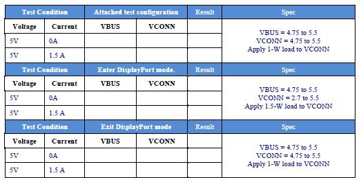
I'm facing an issue using TPS65982 when running the "Vbus and Vconn Verification Test" using GRL-USB-PD-C1 equipment.

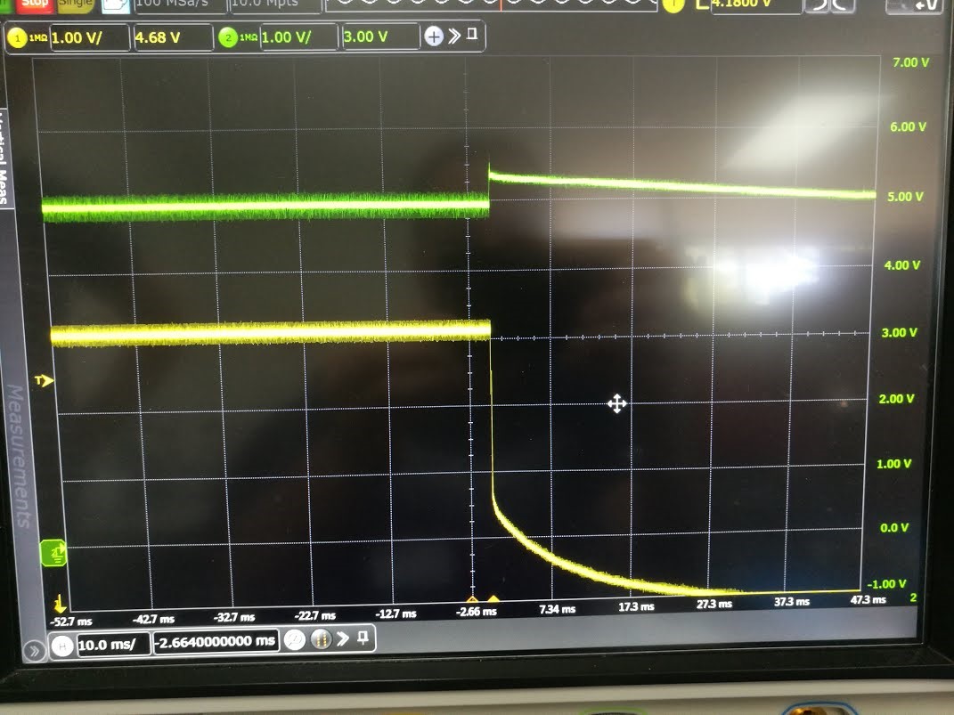
When I apply a load of 1.5W in Vconn, voltage values are ok. But when I change the load from 1.5W to 1.125W Vbus goes to zero and from CTS it needs to stay between 4.75V to 5.5V.

Looking at the attached figure I was able to check that a spike is generated in Vconn and then Vbus goes to zero.

Is there any way to prevent this to happen? Some TPS65982 configuration?

I was not able to find anything to prevent this kind of phenomenon in Vconn.

  • Hi Andre,

    Can you measure VCONN current during the failure? It seems like there is a load spike when the power consumption transitions from one level to another. Additionally, can you include PP_Cable voltage in your scope capture?

    Thanks,
    Eric
  • Hi Eric,

    Vconn current is 1.5A.
    It's not easy for me to probe PP_Cable, because I don't have any test point in my board.

    But do you think it can be a limitation of the Voltage/Current that I'm providing to PP_Cable pin?
    I'm using TPS61230DRCR. Should be able to provide 5V/2A.
  • Hi Andre,

    The VCONN current supported by TPS65982 is 600mA. If the VCONN current is 1.5A, this spec is violated and the TPS65982 will open the VCONN Switch due to over-current.

    Thanks,
    Eric
  • Hi Eric,

    GRL-USB-PD hardware/software is applying the following steps (showed below), where we need to have Vbus/Vconn values between the Spec values.

    I think that 1.5A are applied to Vconn. Do you agree?

    But I can't understand the relation between this 1.5A and the 1W and 1.5W load that we need to apply to Vconn.

    One more input to the issue I'm facing. When the load changes from 1.5W to 1.125W Vbus goes to zero. After perform a reset of the TPS65982 Vbus is again 5V.

    But during compliance test it's not expected that we perform a reset of the chip, right?

  • Hi Andre,

    It looks like that test is applying 1.5A on VCONN, this would exceed the spec of the TPS65982 and cause the PD controller to open the VCONN FET due to over-current protection.
    After the device opens the VCONN FET, the connection should restart. The device should not have to be reset. It would automatically retry making a connection.

    Thanks,
    Eric
  • Hi Eric,

    If you look at the scope capture above (where Green - Vconn and Yellow - Vbus) we have a spike in Vconn but then it continues with 5V.
    The issue is that Vbus goes from 5V to 0V.

    Looking at the Utilities GUI we have overcurrent protection in Vbus but not in Vconn. My assumption is correct?

    If in Vconn we continue with 5V I assume that Vconn FET is not opened due to over-current protection, right?

    To automatically retry making a connection I need to configure a GPIO event?
  • Hi Andre,

    The TPS65982 has overcurrent protection on both VCONN and VBUS. VCONN current protection is not adjustable and is set to 0.6A based on the Spec of the VCONN FET.
    Nothing special needs to be configured to do auto-retry. The PD Controller will do this automatically.

    Thanks,
    Eric