This thread has been locked.

If you have a related question, please click the "Ask a related question" button in the top right corner. The newly created question will be automatically linked to this question.

THVD1550: replace MAX13487EESA+T

Part Number: THVD1550
Other Parts Discussed in Thread: NA555, SN74LVC1G123

Hi Sirs,

Sorry to bother you.

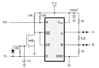
We are plan use THVD1550 to replace MAX13487EESA+T.

We saw MAX13487EESA+T include auto direction function but TI didn't.

So, could we use THVD1550 to replace MAX13487EESA+T? have any risk?

If couldn't, does TI have others solution can share?

Thanks!!

  • Hello Shu-Cheng,

    There are a couple of different approaches for automatically controlling the direction of the RS-485 transceiver.  The MAX13487 device implements this by only actively driving the low signal level and going high-Z for high levels (making them electrically the same as an “idle” or receive-only mode).  This has the drawback in that the effective driver output strength for high levels (and corresponding high-level voltage output) is reduced below what is typically required by the RS-485 standard.  A similar approach can be implemented with THVD1550 using a few additional components; I’ve drawn a schematic demonstrating this below:


    A low signal on TX makes the output driver active with a low-level output state.  A high signal on TX disables the driver, allowing for a high level to be held on the bus via the pull-up/pull-down resistances.  The RC circuit on the gate of the FET is present to slow down the turn-off of the driver on a rising edge of the TX line.  This allows the driver to remain active for a short period on a low-to-high transition to help quickly drive the bus to a high state before releasing it.  The component values can be adjusted based on the required data rate and maximum expected parasitic capacitive loading, and the RC circuit may not be needed at all for lower data rates.

    To help illustrate this theory of operation, here are some example switching waveforms for the D and DE inputs as well as the gate of the FET used:


    Another approach that is able to maintain full compliance to the RS-485 standard requirements is to use a timer to enable the output driver for a fixed period of time (equal to one data frame) whenever data is present on the TX line.  This is more equivalent to how an MCU would typically control the DE/RE lines of the transceiver.  For a reference implementation using NA555 as a timer circuit, you can reference TIDA-01090.  A similar solution using SN74LVC1G123 is given in TIDA-060008.

    Please let us know if you have any further questions.

    Best regards,
    Max