This thread has been locked.

If you have a related question, please click the "Ask a related question" button in the top right corner. The newly created question will be automatically linked to this question.

TPS65981EVM: TPS6598x Application Customization Tool version 4.03 can't communicate with device

Part Number: TPS65981EVM
Other Parts Discussed in Thread: TPS65981,

The Application Customization Tool can't seem to communicate with the TPS65981 via the FTDI board.  From observations using a scope it seems that the tool is using the wrong port on the FTDI chip for SPI and I2C communication.  When I look at the serial clock pins it looks like I2C clock is on the SPI clock pin and vice-versa.

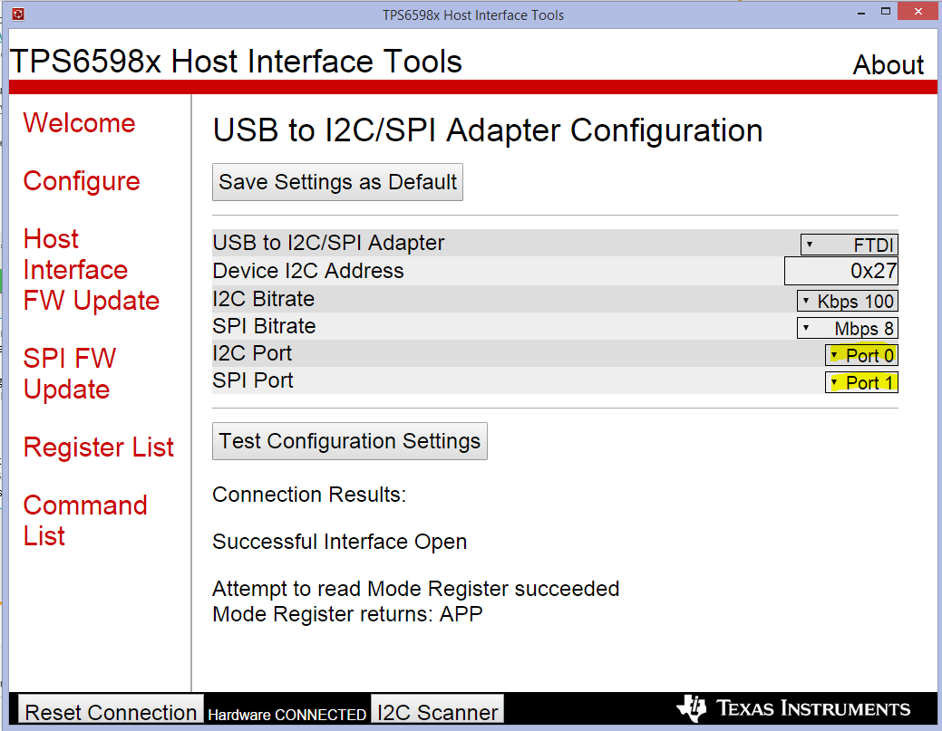
When I run the TPS6598x Host Utilities GUI Version 2.3 which I understand is out of date, I have to swap the default ports used for I2C and SPI before it succeeds:

So, this leads me to believe that for whatever reason the wrong ports on the FTDI device are being used for I2C and SPI communication.  Is there a way with the Application Customization Tool to select the FTDI port used for SPI/I2C communication as can be done in the TPS6598x Host Utilities GUI Version 2.3?

Thanks.

  • Hi JEB,

    I can't reproduce the failure you are reporting. I can assure you that the hardware is connected correctly between the FTDI and TPS65981 on the TPS65981EVM. The TPS65981 can only be communicated to during run-time over I2C, the SPI lines are only used if you want to update the image stored in the SPI Flash chip.

    Please ensure you are using the latest version of the Tool from TI.com. I would suggest doing an I2C sweep in the tool to find the correct address, you can do so by clicking Debug --> Configure I2C/SPI Adapter Options --> Select FTDI --> Select Sweep I2C Address Range for Response.

    If this answers your question, PLEASE select This resolved my issue

    Thank you,
    Eric

  • Thanks for the response.  I wasn't questioning the HW connection, but rather the ports that end up getting used by the Application Customization Tool for the I2C bus and the SPI bus.

    I am using the "TPS6598x Application Customization Tool version 4.03" which is the latest.  The FTDI driver is what was installed with the tool and the FTDI version is 2.12.28.0.

    Yes I did an I2C sweep and it fails.  It you look at the user guide page 19, J8, when I do the sweep I see a 400 KHZ clock with 9 clock pulses (seems like a typical I2C clock to me) coming out of pin J8 pin 13 which connects through a resistor to the F_SPI_CLK net.  When I run the "TPS6598x Host Utilities GUI Version 2.3" I have to change the ports used for the I2C and SPI bus before the test succeeds and then the I2C SCL/SDA signals are on the right pins.  The fact that I have to reverse the ports to get the I2C SCL on the right pin with the Host Utilities tells me that there is something swapped between the apps and the driver.

    It looks to me like for whatever reason, maybe between the driver and the app, the wrong ports are used by the tools.  I can see with a scope where the I2C SCL is when I run the I2C sweep and it ends up on the SPI_CLK pin.  It is a pretty simple thing for me to see with a scope.  What I want to know is whether or not I can swap ports used by the "TPS6598x Application Customization Tool version 4.03" like I can with the ""TPS6598x Host Utilities GUI Version 2.3".

  • Hi JEB,

    I have not yet been able to reproduce this behavior on my 81 EVM setup.
    When you open tool version 4.03 can you click Debug --> Configure I2C/SPI Adapter Settings and then select FTDI and "Sweep I2C address range for response"?
    If you see a failure, can you please include a screenshot of it in your response?
    When I run this test, I see the expected I2C address of the TPS65981 come up.

    Thank you,
    Eric
  • Hey Eric,

    Thanks.  From what I can tell there seems to be some variability to how those ports get set up by the FTDI driver.  So Saturday and yesterday I couldn't get the customization tool to communicate over SPI (the evm recovery  firmware download would fail during verification), and the various I2C commands wouldn't work like scanning the I2C bus, manually setting the I2C address to 0x27 and performing the test I2C read.  But yesterday, I got my hands on the second EVM we have in house, connected it and I was able to download the EVM firmware and use the I2C bus for debug.  I did notice in the Windows device manager that different com ports were created which is typical when FTDI devices are plugged in to different ports or a different FTDI device is connected to the same port.  Now today I was able to communicate with both of the EVMs.  So, like I said it just seems like their is some variability that happens when connecting these to different USB ports and how the FTDI driver assigns them.  But that is just a guess for now.

    Thanks

  • Hi JEB,

    Thanks for the clarification. We have had many issues with using the FTDI and its various drivers in the past. We are considering switching to a different USB to I2C/SPI chip for future EVMs we develop. Different FTDI Driver versions work better on some computers than others. We included a few different driver version in the GUI installer to try and help with this issue. It sounds like you loaded a different FTDI driver when switching EVMs which resolved your issue.

    Please let me know if anything else is needed for this ticket.

    Thank you,
    Eric
  • I didn't change the FTDI driver, but I think different COM ports were enumerated when I connected the second EVM.

    Thanks.