This thread has been locked.

If you have a related question, please click the "Ask a related question" button in the top right corner. The newly created question will be automatically linked to this question.

LVCMOS33 to RS422 transceiver

Other Parts Discussed in Thread: AM26LV31E, AM26LV32E

Hi,

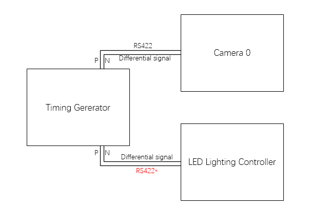
    I have 8 channels of LVCMOS signals (3.3V) from FPGAs, and now I need to convert these 8 channels of LVCMOS signals to RS422.

    The maximum frequency of the LVCMOS signal is 20kHz. Lower signal transmission delay ( < 50 ns), higher output driver ( >20mA ) and ease of use are basic requirements.

    Could anyone please give me some suggests for my project. Is there some chip can meets my needs?

   Thanks all.

  • Hi Penn,

    In my opinion the simplest solution here would be to use two AM26LV31E devices. Could you please take a look over that device's datasheet and let us know if you have any questions or concerns?

    Regards,
    Max
  • Thanks for your reply.

    I am sorry that I reply you so late.

    I have just taken a look over the AM26LV31E datasheet. Could I consult another question to you?

    In my project, the power supply is 3.3V. RS422 level is used to control the latter controller, the input of the controller is isolated by the optocoupler.

    The controller's datasheet requires the input voltage of 3.3v-5v and the input current greater than 20mA.

    But in AM26LV31E datasheet Page 1 : "Differential Output Voltage With 100-Ω Load: 2.6 V Typical". So I think AM26LV31E is not suitable for my project.

    Is my conclusion correct? if NOT, could you give some detail explain for me ?

    Best Regards.

    Penn

  • Hi Penn,

    I'd like to make sure I understand what kind of input your controller requires.

    A common implementation would be to have RS-422 differential inputs and use a receiver device (like AM26LV32E) to convert the differential signal to a single-ended signal (with high level of 3.3 V or 5 V) in order to drive the opto-couplers. In this case an RS-422 transceiver like AM26LV31E would be suitable for driving the inputs since the translation to 3.3 V/5 V would happen internally to the controller.

    If the controller input connects directly to the opto-couplers and if the opto-couplers require a 3.3 V or 5 V signal, then it typically wouldn't make sense to use an RS-422 transmitter to drive them. (Typical RS-422 differential signal levels are 1.5 V minimum.)

    Do you have something like a schematic or block diagram of the controller that you could share?

    Regards,
    Max
  • Hi Max,

    Application Strategy as follow:

    1: The timing generator is designed with an FPGA by our company, and LED Controller is produced by other manufacturers.


    2: The output channel of the Timing Generator needs to be arbitrarily switchable.


    3: In the datasheet of LED Lighting Controller, I haven`t found out what level standard of the input signal. I have consulted the technical engineer of the manufacturer and they told me that the level standard of the input signal is in accordance with RS422, but I found a description of the input signal in the datasheet (input voltage range is 3.3V-5V, input current Is 20mA) . So we're getting confused for that.

    LED Controller input block diagram is shown follow:

    So I don't know how to design the output of the timing generator.

    Best Regards,

    Penn

  • Penn,

    Thanks for the clarifications - this is very helpful.

    It looks like the LED controller input was designed to accept a 3.3-V or 5-V input on External Strobe+ (with External Strobe- grounded) and then uses the 220-Ohm resistor to limit the forward current through the opto-coupler to <20 mA.

    It will probably still work when driven by an RS-422 driver (especially if the input was specified to accept RS-422 signals), but the voltage between External Strobe+ and External Strobe- may not meet the 3.3 V minimum requirement. (A smaller voltage here would make the forward current smaller, meaning that the LED is dimmer and the photo-transistor may not turn on as strongly.)

    I would confirm this operating with the manufacturer if possible. Right now it appears that there is an inconsistency in the input specification in requiring a larger voltage than the RS-422 standard generally supports.

    Regards,
    Max
  • Hi Max,

    After reading your reply, I`m more certain that the LED controller`s input does not meet any common differential level standard.

    As you said: "an inconsistency in the input specification in requiring a larger voltage than the RS-422 standard".

    So I will use the output signal of RS422 for system testing, and then choose a more appropriate strategy in the system design to ensure that the circuit can run normally.

    Thank you for all that you have done.

    Best Regards,

    Penn