This thread has been locked.

If you have a related question, please click the "Ask a related question" button in the top right corner. The newly created question will be automatically linked to this question.

TUSB1210: CPEN Open Source vs Open Drain mode

Part Number: TUSB1210

My TUSB1210 is setup as a Host PHY transceiver, as shown on data sheet page 48. It is connected to a USB Device. VBAT (3.3V) and VDDIO (1.8V) are applied.

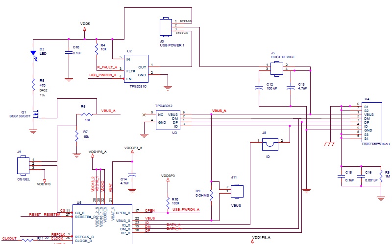
I have the option of connecting 5V directly to VBUS or I can use TUSB1210 CPEN pin to enable a VBUS switch that will pass 5V to VBUS. VBUS is connected to TUSB1210 VBUS pin and VBUS pin of USB port.

My CPEN pin has a 100k ohm pullup resistor to 3.3V. This is also what is shown in the TUSB1210 evaluation schematic, see attached picture below.

I would like to detect when a Device is connected to the USB port.

My idea is as follows:

Write to VENDOR_SPECIFIC3 register (0x85) bit 4 CPEN_ODOS with a 1 to place CPEN pad in OD (Open Drain) or OS (Open Source) mode.

Then use VENDOR_SPECIFIC3 register (0x85) bit 5 CPEN_OD, already reset to a value of 0, to use CPEN pad as OS (Open Source).

What does active LOW mean in this case? Is this before or after CPEN output pin sees the attached Device?

Can I expect my CPEN pin to be pulled HIGH to enable my VBUS switch when a Device is connected to my USB port?

Then write to USB_INT_EN_RISE register (0x0D) bit 1 VBUSVALID_RISE with a 0 to clear the bit, I'm assuming that when VbusValid changes from a LOW to a HIGH it will set bit HIGH.

Then I will interrogate the USB_INT_EN_RISE register (0x0D) bit 1 VBUSVALID_RISE and look for a 1 indicating that VbusValid changed from a LOW to a HIGH.

Is my understanding correct?

Or is there another (easier) method to determine when a Device is attached to my USB port?

Instead, can I just look at USB_INT_EN_RISE register (0x0D) bit 0 HOSTDISCONNECT_RISE?

Thanks, Roland

  • Roland

    DRVVBUS and DRVVBUSEXTERNAL bits (OTG_CTRL register, bits 6 & 5) must be set to 1 in order to to set Pin17 (CPEN). Please notice that the reset value for both registers is 0.

    For device connection, I would refer to the USB On-the-Go spec. The detection depending on the combination of host and device type.

    Thanks
    David
  • David,
    Ok, setting DRVVBUS and DRVVBUSEXTERNAL bits to a 1 enables the CPEN OUTPUT.

    To detect when a Device is connected to the USB port, do I still:
    Then write to USB_INT_EN_RISE register (0x0D) bit 1 VBUSVALID_RISE with a 0 to clear the bit, I'm assuming that when (VBUS is applied) VbusValid changes from a LOW to a HIGH it will set bit HIGH.

    Then I will interrogate the USB_INT_EN_RISE register (0x0D) bit 1 VBUSVALID_RISE and look for a 1 indicating that VbusValid changed from a LOW to a HIGH (VBUS is applied).

    Is my understanding correct?
    Thanks, Roland
  • Roland

    It depends on the type of host, device, usage case and this is covered in section 2.1.1 of the OTG spec, which I copied below.

    For the use cases described below there are a variety of ways to initiate a USB connection. However, in each case, power must first be provided to the attached device. The most basic cases involve either:

     A wall-powered Embedded Host that provides power via the downstream port at all times or
     An insertion-based A-device which provides power via its port as soon as an A-plug is attached and continues to do so in either host or peripheral role:
    o An OTG A-device or EH can detect insertion of a Micro-A plug into a Micro-AB receptacle by detection of the ID pin becoming FALSE.
    o Embedded Hosts can detect insertion of a Standard-A plug into a Standard-A receptacle by using mechanisms described in [USBPower1.0].

    Since a USB A-plug is attached to the power provider in both of these cases, in the following text we will refer to this as the USB A-port. If the Embedded Host or OTG A-device does not normally provide power via its USB A-port, when not actively communicating with another device, there are several ways to restore this power supply.

    1. If the only host applications that use USB are user-initiated, then power is provided via the USB A-port when the user initiates one of these functions.
    2. Any OTG A-device or Embedded Host that does not provide power via its USB A-port while a cable is attached, and has an SRP-capable peripheral on its Targeted Peripheral List, should power the USB A-port in response to user input on the attached device.
    3. If the device has applications that will run automatically as soon as attachment to a particular device is detected, then it is required in this particular case that these devices support the Attach Detection Protocol (ADP). The device detects device attachment changes using ADP.
    a. When a change is detected, by an A-device it will start providing power via the USB A-port. If no device is connected, power is turned off again. If the presence of a device is detected, then the A-device queries the device type, etc.
    b. When a change is detected by a B-device it will issue a request for power to be turned on (SRP). If no device is connected power will not be provided. If power is detected then the B-device will respond to queries for device type etc.

    Are you worried about saving power? If power saving is not a concern, then the simplest solution is to enable VBUS all the times, and then wait for device connection. Or have the power off first, but once the device is connected, do an external user-initialized sequence to enable VBUS.

    Thanks
    David

  • Hello David,
    This question is in relation to my post: TUSB1210: Implement KVM over fiber with TUSB1210,
    e2e.ti.com/.../755953

    I am not worried about saving power.
    I do not have any OTG devices.

    My question is knowing when a device (keyboard, video, or mouse) is attached to the Hub on the Client Side, see Block Diagram from other post.
    What do I query on the Client Side TUSB1210 Host PHY that tells me when one or two or three devices are attached?
    I would then have to transmit this info (device attached) to the Host Side, so the HOST PC can initiate enumeration.
    Once a device is attached on Client side, I can pull in the 1.5k ohm pulldown on the Host Side TUSB1210.
    How can I distinguish if I have a keyboard, video or mouse device attached to the hub?
    How can I tell the Host PC that I have a keyboard, video or mouse attached?
    Thanks, Roland
  • David will be back next week.
  • Roland

    If power is not an issue, please set DRVVBUS and DRVVBUSEXTERNAL bits (OTG_CTRL register, bits 6 & 5) to 1 so CPEN is always enabled and provided 5V VBUS to the hub.

    The Hub Class defines one additional endpoint beyond Default Control Pipe, which is required for all hubs: the Status Change endpoint. The host system receives port and hub status change notifications through the Status Change endpoint. The Status Change endpoint is an interrupt endpoint. If no hub or port status change bits are set, then the hub returns an NAK when the Status Change endpoint is polled. When a status change bit is set, the hub responds with data. So when keyboard/video/mouse is attached, the Status Change endpoint will change from NAK to data. Separation of keyboard/video/mouse is done as part of the enumeration process. You can then use this data to determine which status register to access in order to determine the exact cause of the status change interrupt. The block diagram is Figure 11-21 of the USB2.0 spec.

    The 1.5k pulldown on the host side of TUSB1210 is only used between TUSB1210 and hub. Hub has 1.5k pulldown on its downstream port. So when keyboard/video/mouse is attached, hub will enable its 1.5k pulldown.

    Thanks
    David
  • Roland

    Does my answer address your question?

    Thanks
    David
  • Hello David,

    Sorry for my delayed response.

    Thank you for your responses to my questions. 

    Your explanation was very good to what the hub returns to the host on the Status Change EP when a keyboard/video/mouse is attached.

    I still have to review which status registers I can access to determine the exact cause of the status change interrupt.

    Thanks, Roland

  • Roland

    Hub status change is covered in Section 11.12.3 of USB2.0 spec.

    Thanks
    David
  • David,
    You mentioned previously "The 1.5k pulldown on the host side of TUSB1210 is only used between TUSB1210 and hub."
    1 - Where do I pull in this 1.5k ohm pulldown on the TUSB1210? Is this an internal TUSB1210 resistor?
    2 - When would the TERMSELECT 1.5k ohm pullup get pulled in from the FUNC_CTRL register?
    3 - By default, the OTG_CTRL register DMPULLDOWN and DPPULLDOWN are set to 1, meaning pull-down resistors connected to D- and D+, respectively. Under what circumstance would this resistors not be connected to D+ and/or D-?

    Thanks, Roland
  • Roland

    I think the 1.5k pulldown is a type, it should be 15k pulldown.

    Please see this table, this table summarizes different USB bus condition and answers your question 2 and 3.

    Thanks

    David

  • David,
    OK, so you said that the 1.5k ohm pulldown is a typo and s/b 15k ohm.
    Where did you find the Table that summarizes the different USB bus conditions?
    Thanks, Roland
  • Roland

    This was covered as part of the ULPI spec: www.sparkfun.com/.../ULPI_v1_1.pdf, Table 41.

    Thanks
    David
  • David,
    Yes, Table 41 , page 82, of UTMI+ (ULPI) spec shows the table of interest.
    Thanks, Roland