This thread has been locked.

If you have a related question, please click the "Ask a related question" button in the top right corner. The newly created question will be automatically linked to this question.

TCA9617B: EN pin, which voltage should be applied?

Part Number: TCA9617B
Other Parts Discussed in Thread: TCA9517,

We may have found an error with the part TCA9617BDGKR in our schematics that results from your datasheet. http://www.ti.com/lit/ds/symlink/tca9617b.pdf

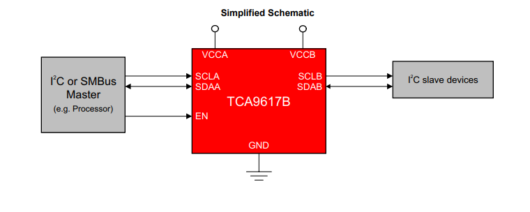
The EN-pin is placed on the VCCA-side or I2C-master side in the first figure of the datasheet.

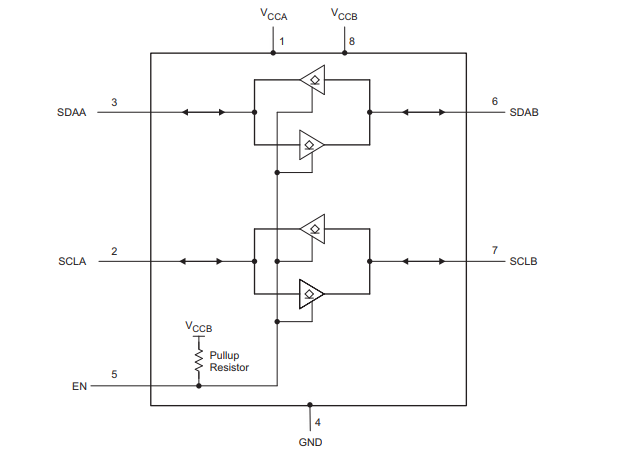
Later in the datasheet we can find this figure:

Here we can see that EN is not tied to VCCA but VCCB. 

So here are my questions:

So does anything bad happens to the part and is it functioning to its specified behavior if I have the EN-pin tied to +3.3V (VCCA) and VCCB is +5V?

Why is the EN pin internally tied to VCCB when it makes more sense to be triggered by the master (VCCA-side) and not the slave (VCCB-side)?

  • Hey Sebastian,

    "So does anything bad happens to the part and is it functioning to its specified behavior if I have the EN-pin tied to +3.3V (VCCA) and VCCB is +5V?"

    The device is likely to continue functioning though 3.3V on the enable pin is a little bit below the 70% VccB value for the enable. A minor downside is the leakage current that will flow from VccB to VccA through the internal pull up resistor.

    "Why is the EN pin internally tied to VCCB when it makes more sense to be triggered by the master (VCCA-side) and not the slave (VCCB-side)?"

    The device is bidirectional, the master can side on the B side and slave on the A side and the device would still work. The reason why the TCA9617B ties the internal pull up to VccB is because the enable reference uses 30% and 70% of VccB to disable and enable. This was borrowed from the TCA9517 as both devices are similar and TCA9517 was the building block for this device.

    Thanks,

    -Bobby