This thread has been locked.

If you have a related question, please click the "Ask a related question" button in the top right corner. The newly created question will be automatically linked to this question.

TPS65987EVM: cannot set the communication in the debug mode

Part Number: TPS65987EVM

Hello!

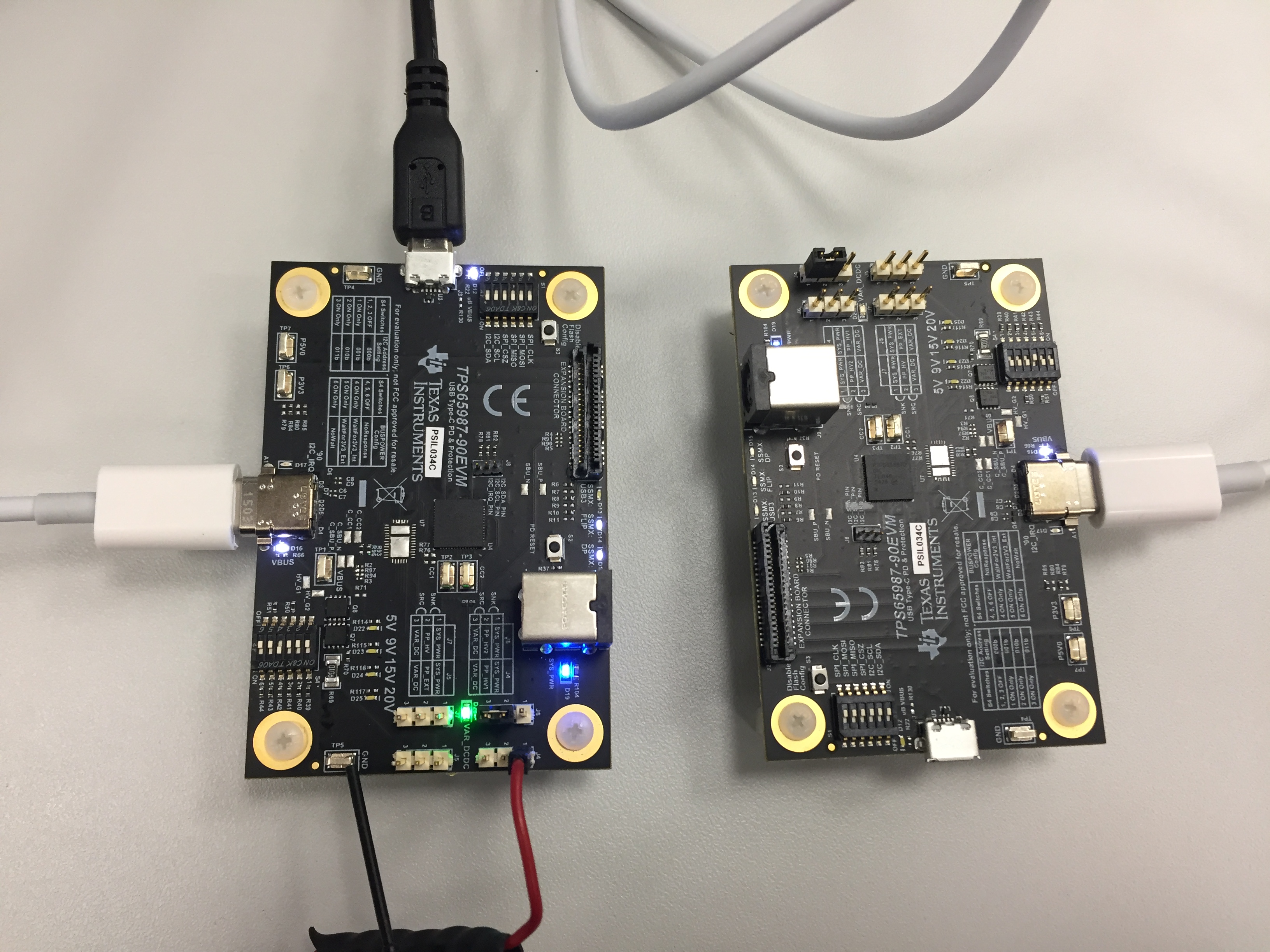
I would like to use TPS65987EVM as a source to deliver 20V/max current (5A ?) via USB-C. It is clear how to configure the jumpers J6 and J4.
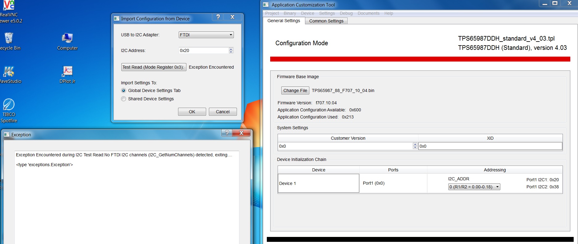
My question is about the variable DC-DC converter. I want to configure it to 20V output (or maybe to bypass it if possible?). To configure it to 20V output I
need to program 3 pins of the USB controller: PDO_1, PDO_2, PDO_3. I tried to use the Application Customization Tool to program them and I could not setup the
communication, so I need your support there.  I used the USB cable for that and did not succeed to setup the communication.

Another question I have is what is the maximum output current the variable DC-DC converter can deliver @ 20V output.

Thanks and Regards,

Natasha

  • Hi Natasha,
    What port partner are you connecting with the EVM? Are you getting 20V/3A PD contract with the default EVM flash image?
    Regards,
    Atiq
  • Hi Atiq,

    I did not connect anything except for the external 20V supply and USB-A-to-B cable to the EVM. I want to configure the EVM as a source to send 20V to the VBUS. What I noticed as well is that none of the LEDs (D22, D23, D24, D25) is ON. As I understand with the standard configuration VAR_DCDC  should deliver 5V, i.e.  D22 should be ON, right? I only see that D19 and D20 ON.

    Regards,

    Natasha

  • Hi Atiq,

    coming back to my question - I would like to set variable DC-DC converter to 20V. For that I need to program PDO_1, PDO_2 and PDO_3 pins and this is exactly where I have a problem. I followed the instructions of the Application Customization tool, but I failed to read/write any registers. I think that the communication does not work. Please see the attached printscreen.

    Regarding my setup - I connected 20V external supply as well as USB A-to micro-B cable.  LED D12, LED D19 and LED D20 are ON. I checked the voltages: both P3V3 and P5V0 present. There is 5V at the output of var DC-DC converter. LED D22 is OFF.

    Why can the communication fail?

    Thanks and Regards,

    Natasha

  • Hi Natasha,

    You need to connect a USB Type-C/PD Sink/UFP port partner to the EVM using a Type-C cable. This would enable 20V PD negotiation and after a successful PD contract TPS65987EVM would provide 20V on VBUS.

    Regards,

    Atiq 

  • Hi Atiq,


    First of all,  for your information - to align - while working with TPS65987-90EVMs I follow 2 documents: “TPS65987-90 Evaluation Module User’s Guide” and “TPS6598x Application Customization Tool”. The first document, page 3 – there is a Figure2, which shows the block level diagram of the EVM. I configure my EVMs according to this diagram.


    I have 2 TPS65987 EVMs. One of them I use as a source, another one as a sink.

    That one which I use as a source, I supplied with the external power supply of 20V. Configuration of J6: pin2 and pin 3 are connected together, meaning that the output of the variable DC-DC converter is connected to PP_HV2. The output of the DC-DC converter sources its output voltage to the VBUS via PPHV2. J4 connector is open (the jumper is removed).

    The second EVM which I use as s receiver (sink) is connected through USB-C cable to the source EVM.  J6 is open and J4 configured as a sink (pin 1 is connected to pin2). 


    The voltage in VBUS is 5V at the moment. And it is clear because the output voltage of the var DC-DC converter by default configuration is 5V.

    I want to control the var DC-DC converter of my source EVM to be able to set the output voltage of the DC-DC converter to 9V or 15V or 20V. For that I need to control the signals PDO_1, PDO_2, PDO_3 and this is where I have a problem because the communication between the GUI and the source EVM does not work. Could you please support me in that!?

    The photo of my setup is attached to this email. The left EVM is the source and the right one is the sink.

    Regards,

    Natasha

  • Hello Natasha,

    I am closing this E2E as we were able to resolve your original issue of not being able to communicate via FTDI. For those having similar problems, the following E2E thread walks through possible ways on how to fix this

    e2e.ti.com/.../2293327