Hi,
As per DP83848I datasheet, MDC looks like a continuous clock in MDC/MDIO interface.
We had performed a theoretical timing analysis and found that an inverter is required on MDC to meet the hold time requirements of DP83848I.
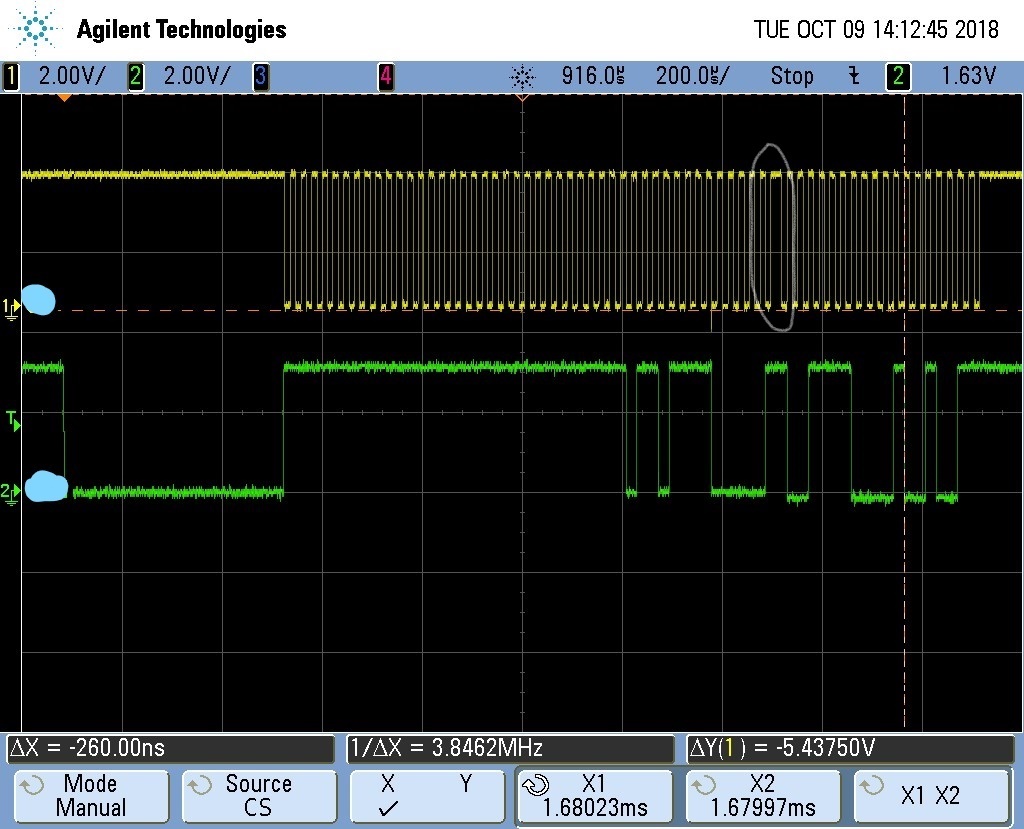
But actual measurement on board, showed that MDC has an intermediate point wherein it stays at high for one cycle and then starts toggling again. The inverter implemented on MDC resulted in hold time failure.
Changing the inverter to a single bit buffer resulted in meeting the timing requirements. We believe that this intermediate point in MDC with no activity is what caused timing failure with inverter implementation. Had the clock been continuous, the inverter implementation would have met the hold timing requirements.
We were also trying to match the MDIO data pattern with that described in datasheet. Though, it matches we are still unable to understand as to why there is inactivity in MDC line even if MDIO data is present.
Please find attached on board MDC and MDIO capture.
Can you please help me understand why MDC has an inactivity for one clock cycle during data transmission?
Regards,
Archana Rao


